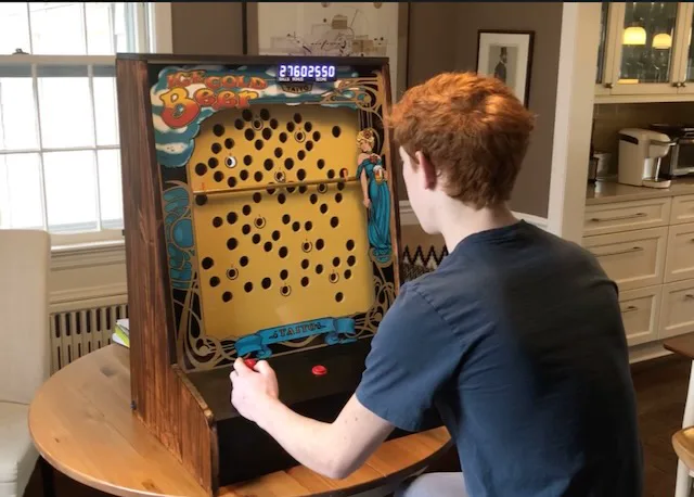
Ice Cold Beer
Full-scale replica of the 1983 Taito arcade game, built from scratch
Background
The original game
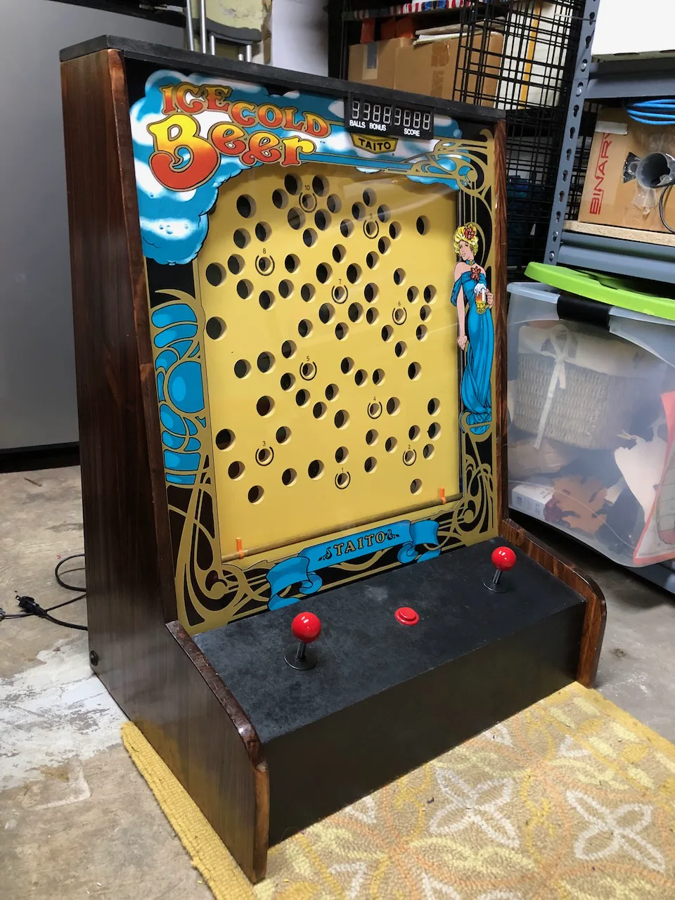
Taito's Ice Cold Beer (1983): tilt a bar to roll a steel ball up a pegboard and land it in a target hole. Original cabinets were selling for $2,000+ — an obvious build challenge.
Constraints
No CNC access, no prior PCB design experience, no large budget. Everything had to work with hand tools, a 3D printer, and Arduino-class microcontrollers.
Scope
Full-scale replica — same playfield dimensions, artwork, and gameplay logic. The project ran June 2020 – January 2023 with long gaps around school.
Build
Result
Deep Dive
Mechanics
Playfield
I did weeks of research: finding pictures and videos of the original games, reading through the owner’s and service manuals, and asking users on vpinball.com for measurements of their Ice Cold Beer machines.
To map out the hole pattern of the original game accurately, I found a reference image online, brought it into Fusion 360, scaled it accordingly, and traced circles over the holes in a 2D sketch. I created a list of X and Y coordinates of each hole relative to the bottom left corner of the playfield and its diameter. Each hole is one of only three different sizes, with the target holes being the smallest.
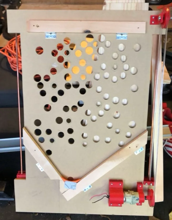
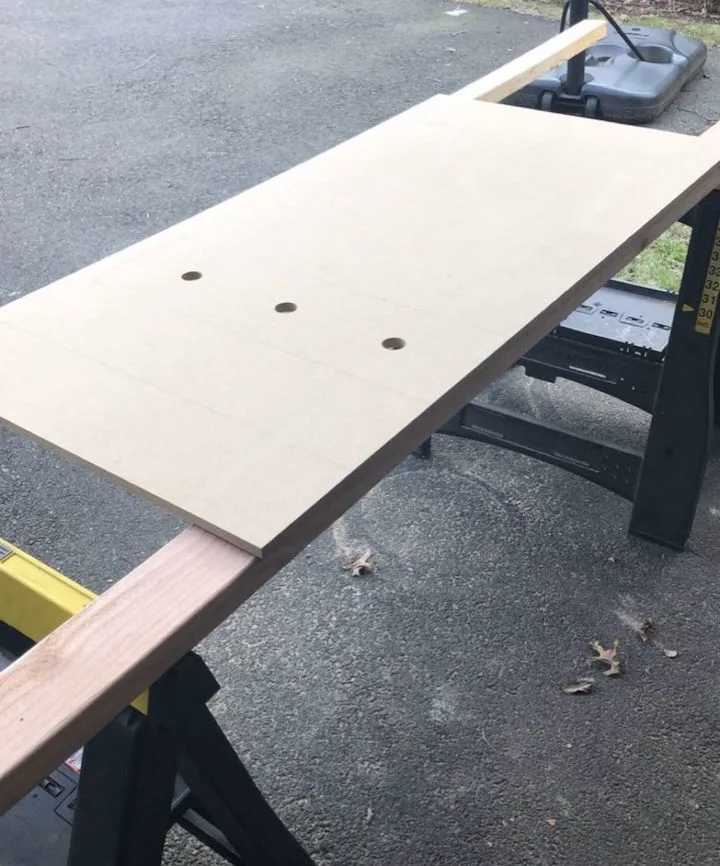
To make the playfield, I got a 1/2 in. x 2 ft. x 4 ft. MDF sheet and three spade bits for my cordless drill. I used a T-square to measure and mark out each hole, color-coding the three different diameters on the MDF sheet. I then drilled each hole by hand with the spade bits and cut out the shape of the playfield with a circular saw.
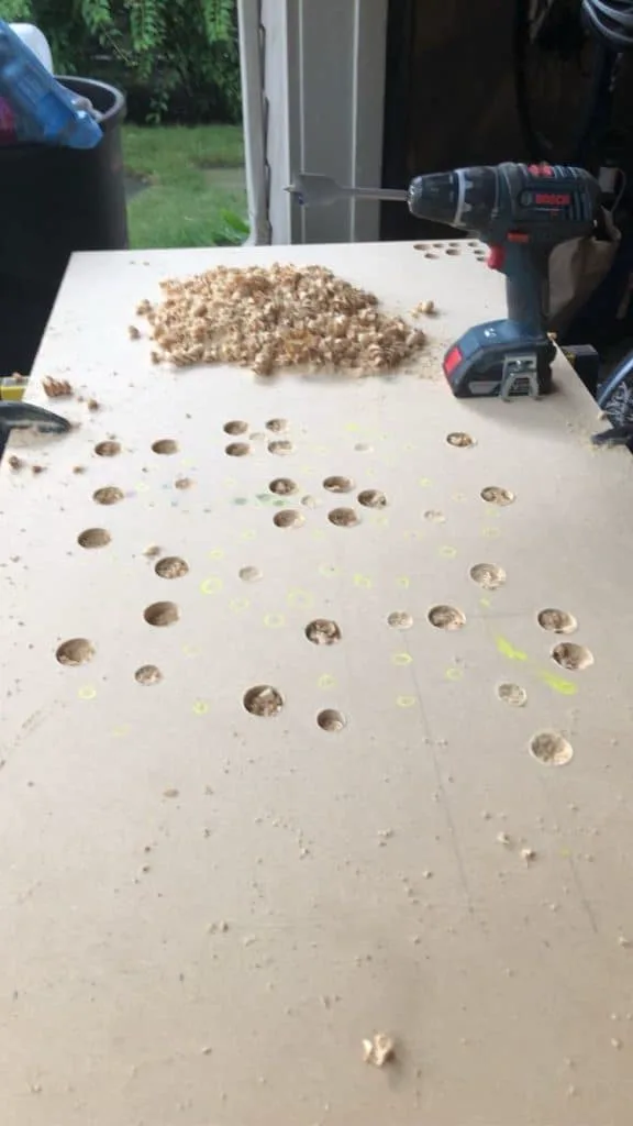
Drilling out the playfield holes with my cordless drill and spade bit
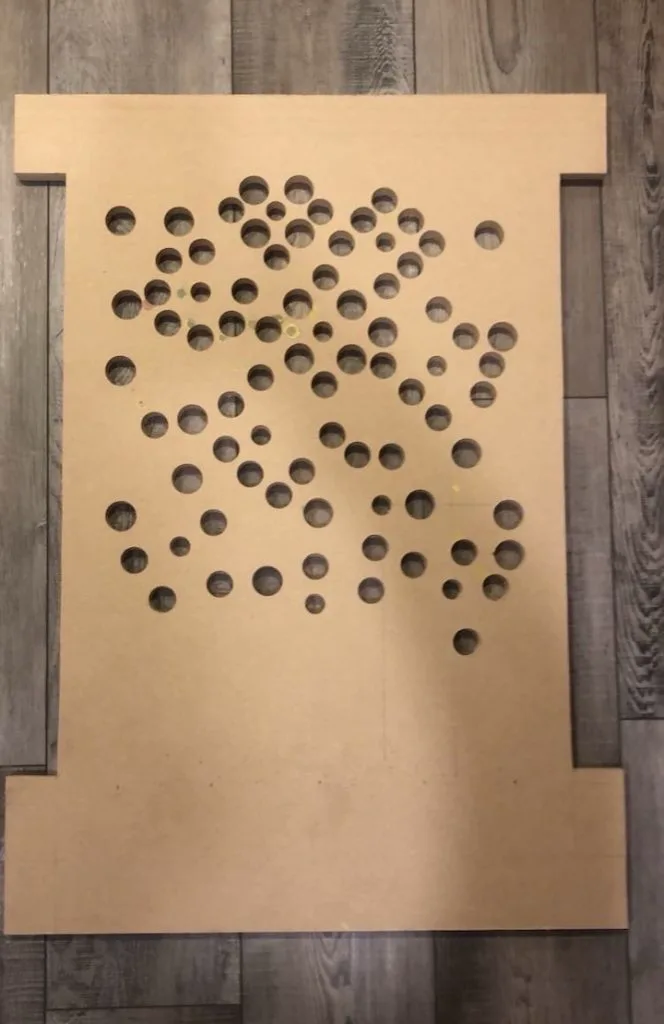
The playfield after all holes were drilled and it was cut out with power saws
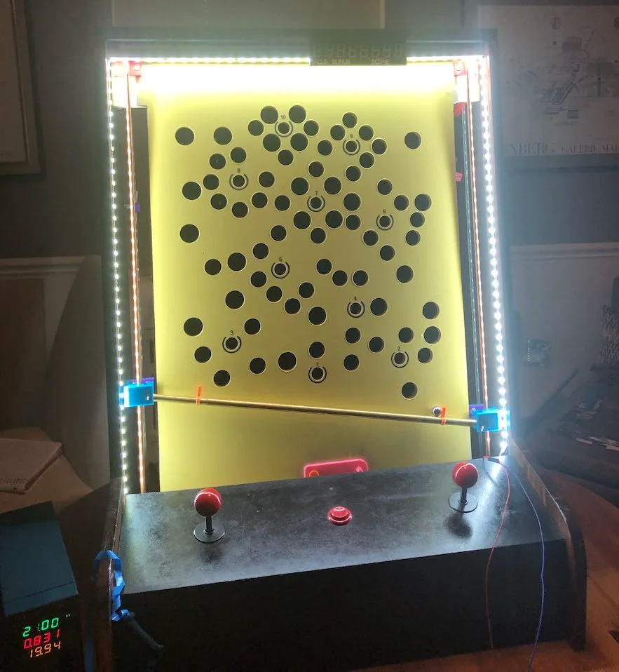
Eventually, I painted the playfield yellow and added circular hole markings (thanks to a 3D printed jig) and stickers for the target hole numbers.
Bar Tilt Mechanism
The bar that tilts in front of the playfield needs to be able to assume any angle within the bounds of the machine. How can such a bar fit inside the cabinet? Well, it’s telescoping! I got two precision telescoping brass tubes with extremely thin walls to act as the main tilting bar.
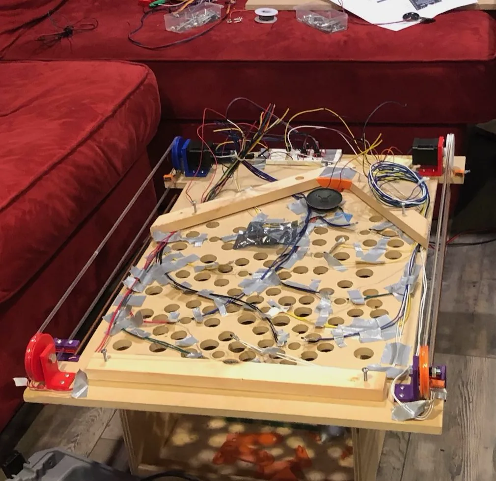
As for the actuation to move each side of the bar, I initially tried a leadscrew approach, but ultimately went with a belt-and-pulley system like the original machine. On the back of the playfield, two NEMA 17 stepper motors with 3D printed brackets, driving pulleys, and idler pulleys independently drive rubber belts up and down the playfield.
Clamped to these belts are 3D printed pieces that clamp to the belt using machine screws and captive hex nuts, slide along the copper guide rod, and allow the brass bar to pivot. I developed at least ten different iterations of this part, to alleviate problems with clamping, sliding, proper bar-playfield gap, and limit switch triggering. As each side of the bar gets pulled in different directions, the bar will naturally telescope appropriately. The belt is cut and gets held in another 3D printed part so it can be tensioned in case it stretches out over time.
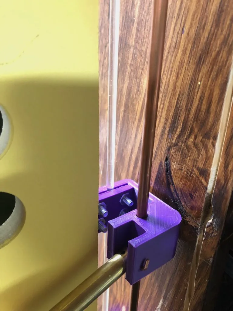
The 3D printed part that clamps to the belt and holds the bar
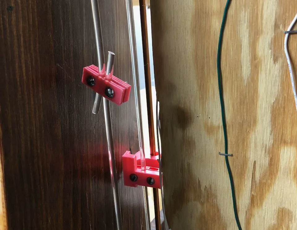
The 3D printed part that uses screws and captive hex nuts to tension the belt
Ball Return
The original machine has a custom vacuum-formed plastic part that carefully guides the steel ball back to the gate where it can be picked up again for the next attempt.
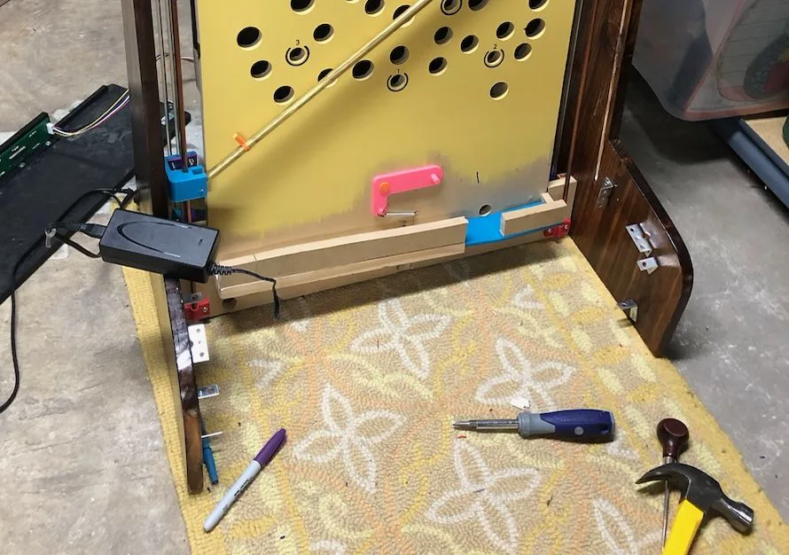
My version takes a much simpler, albeit louder, approach: when the ball enters a hole on the playfield, it falls down until it hits into one of two angled wooden boards that funnel it back to the gate. Since the entire playfield is tilted back ten degrees, I needed a special 3D printed part to bias it forward against the ball gate.
The ball gate is made up of a simple 3D printed part that pivots about a pin and has an operating pin attached. When the bar moves down to retrieve the ball, it pushes the pin as it travels, opening the gate. The ball then falls through the gate onto the bar and tilts down to the right so it doesn’t go back into the gate on the way up.
In very rare cases, it’s possible for the ball to fly forwards off the bar and get stuck in the front of the machine. This is true of the original as well. To combat this, I spent months calculating, designing, and building a solenoid-based return system to shoot the errant balls back in play. When a ball falls off the bar, it falls onto a wooden board attached to the front of the playfield that funnels it to a hole that sends it to the back. From there, it enters a 3D printed chamber and trips an IR sensor, causing the solenoid to energize which forces the steel plunger into the coil and pushes the ball through the 3D printed tube back into play. To optimize the geometry of the tube, I took reference pictures of the playfield and used PTC Creo to project a 2D sketch onto a curved surface to create a 3D sketch that I could sweep a circular profile through. Unfortunately, all this hard work went to waste because the solenoid overheated and burned the playfield, so I decided to scrap the idea. The case of the ball falling ended up being very rare and has proven to not be an issue.
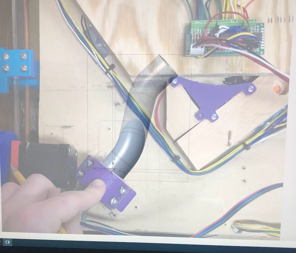
An early version of the swept tube in Creo overlayed on the reference image
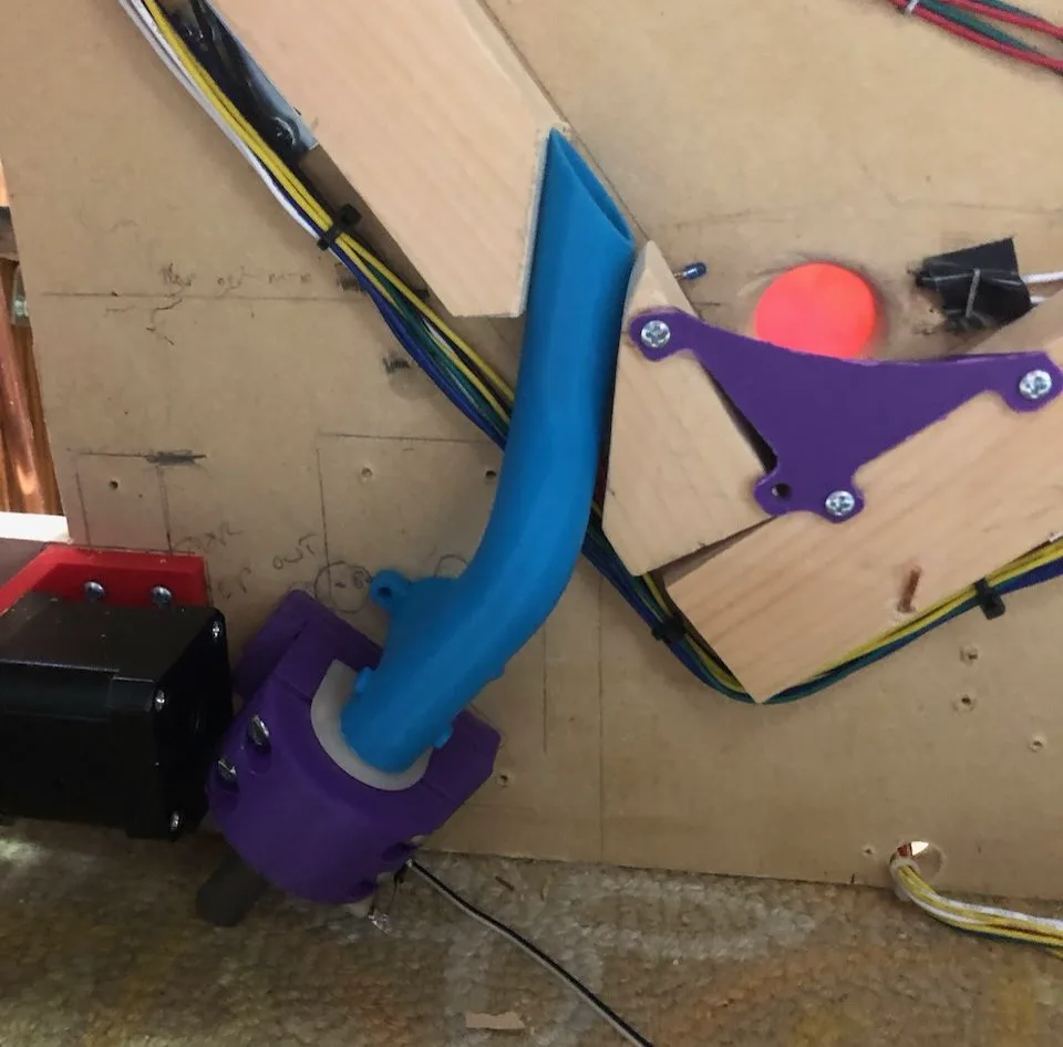
Later, physical version of the solenoid tube
Cabinet
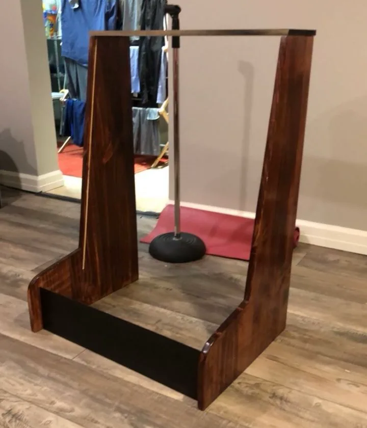
I started with the heart of the machine, the playfield, as a proof of concept. Once I knew the basic mechanics were working, I set out to build a cabinet to hold everything together. The original game uses a full standing cabinet, but I opted for a tabletop version instead.
I sketched out a couple of cabinet designs in Fusion 360 before settling on one and cutting the sides out of 3/4” pine on the jigsaw.
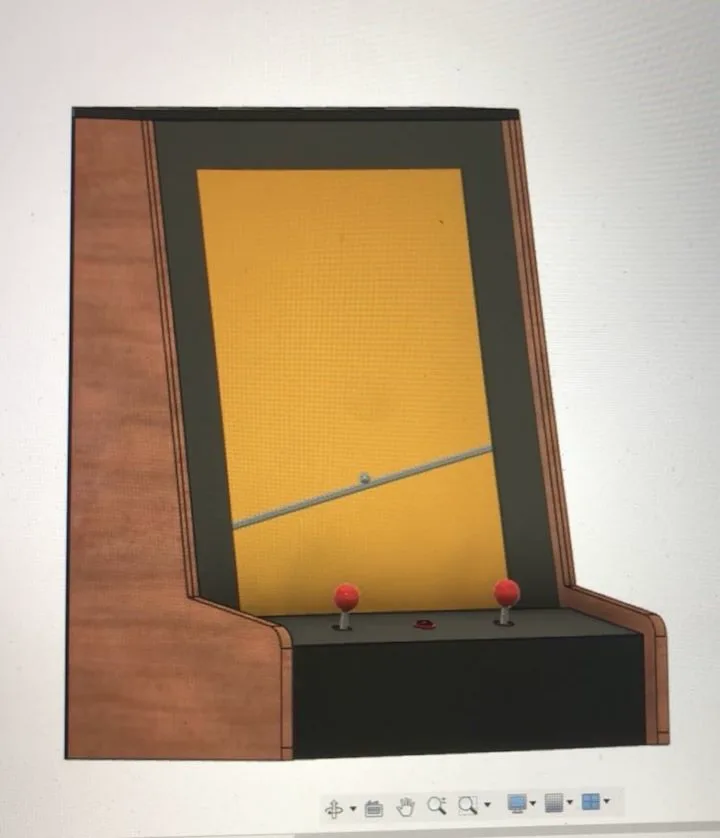
CAD rendering of the cabinet in Fusion 360
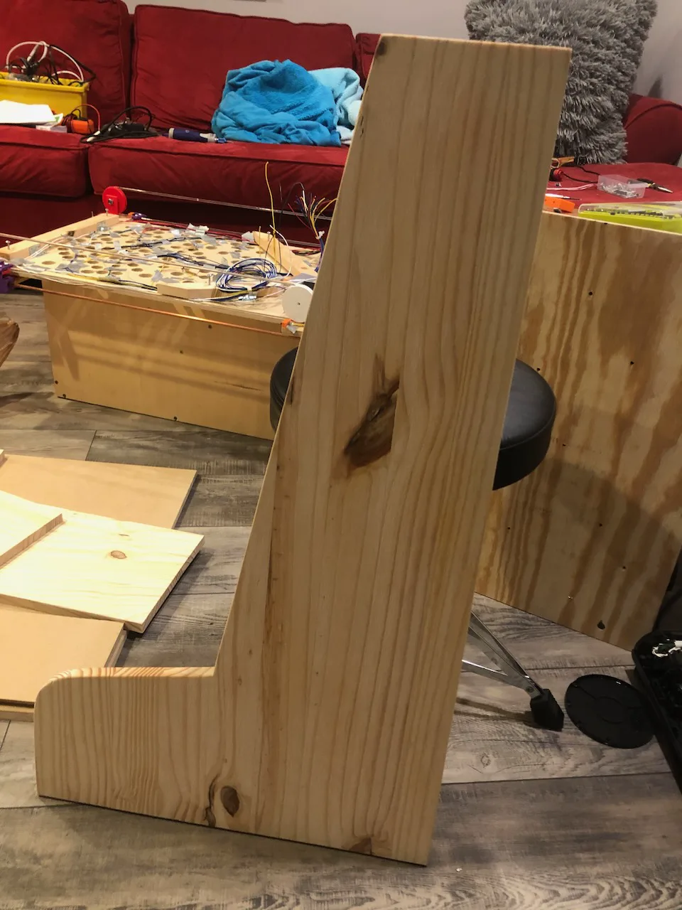
Cabinet side piece cut out of pine
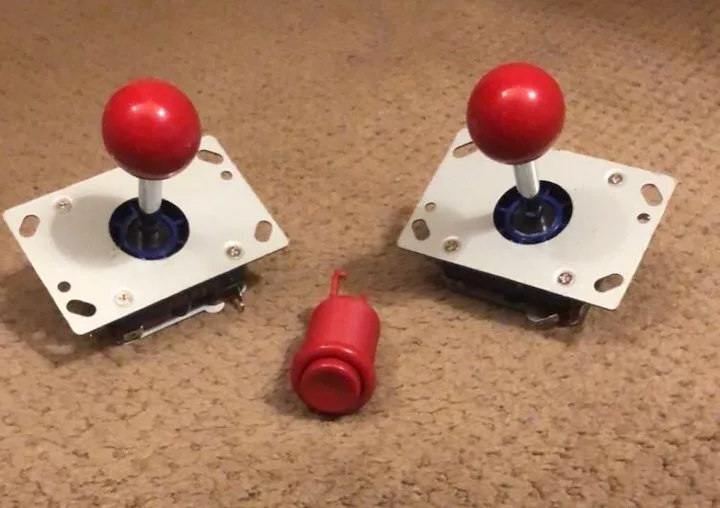
I decided to make the control panel out of the same MDF as the playfield. The top piece of the control panel houses the two joysticks and start button, so I drilled those holes out first before using a circular saw to create the miter cuts to situate everything at the desired angles.
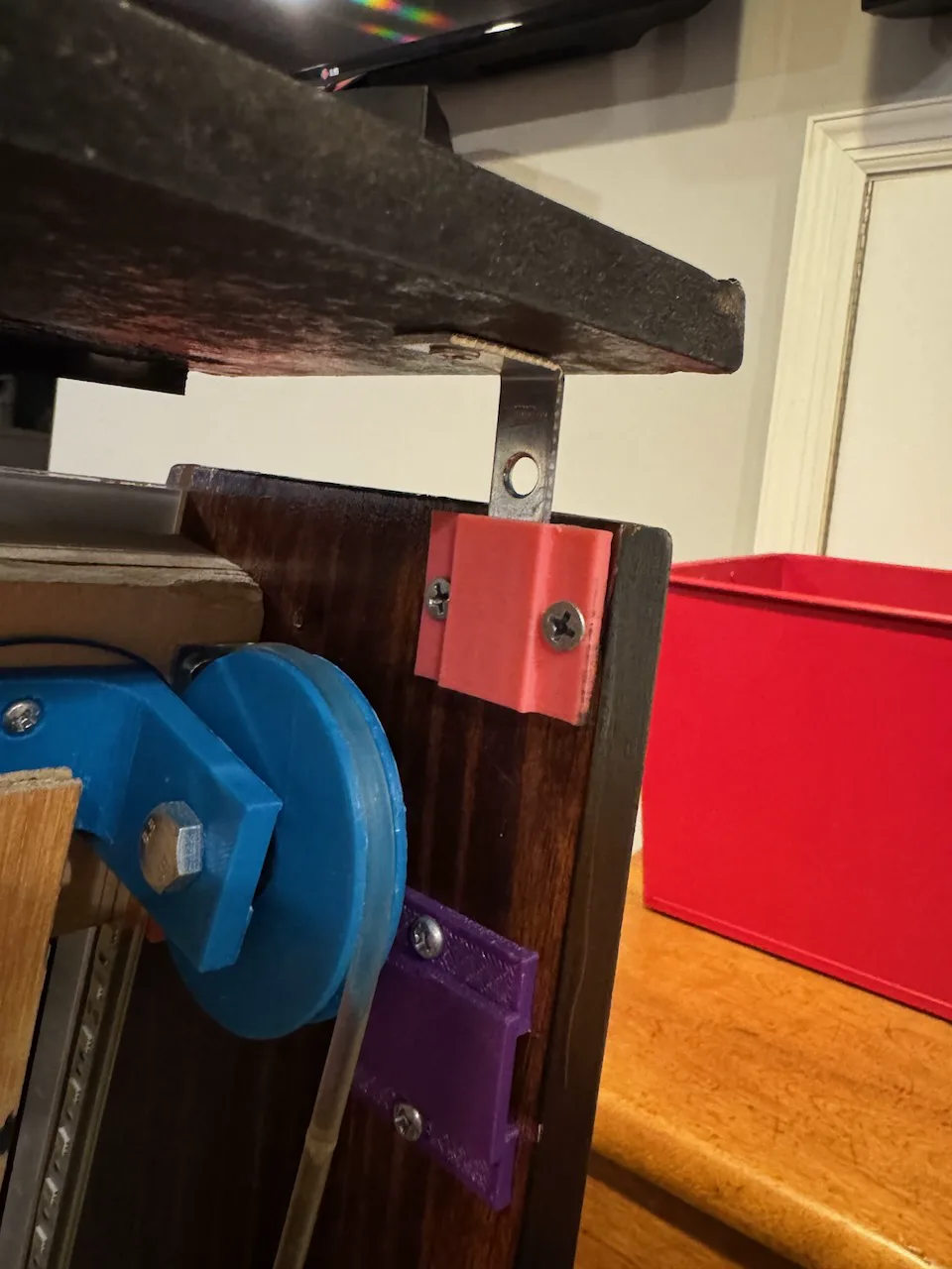
The top of the cabinet is another MDF piece, but it attaches via corner brackets and 3D printed receptacles for easy access to the inside of the machine.
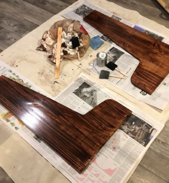
Next, I painted the MDF pieces black and stained the pine pieces with a Mahogany color before coating them in polyurethane for a glossy finish.
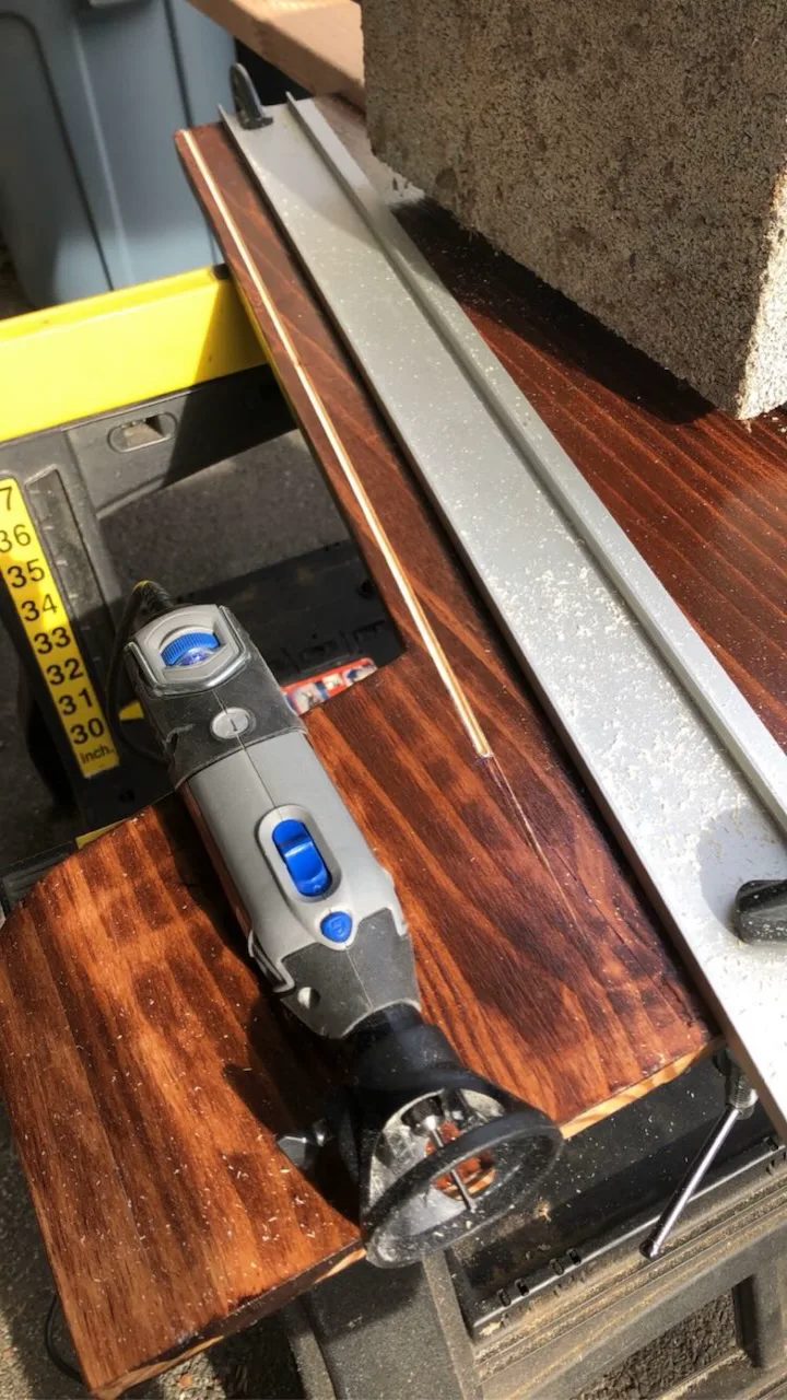
The next step was to install an acrylic panel with artwork. I used a Dremel to route out slots in both sides of the cabinet for the acrylic panel to slide in. In terms of the artwork, I found a copy of the original online, but there were two problems. First, when I started making the machine, I never intended to have artwork, so I didn’t stick to the same dimensions as the original. Second, the artwork I found online was too low resolution to be printed at the scale I needed. I ran the artwork through an AI vectorizer that took the rasterized, pixelated image and turned it into a scalable vector graphic, comprised of curves. Then, my friend Jake helped me manipulate the artwork to fit the proper dimensions of my machine. I got it printed as a vinyl sticker and the vendor used a laser to precisely cut out the inside of the artwork to the boundary line I created.

Edited artwork in graphic design program with red cutting line for laser to follow

Excitement from applying the vinyl sticker to the acrylic sheet
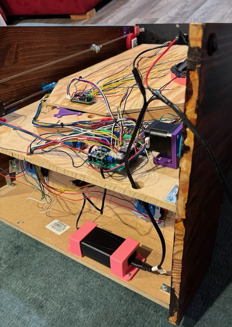
Finally, I used corner brackets and screws to assemble the cabinet together, including the playfield in the middle.
Four pieces of the cabinet assembled
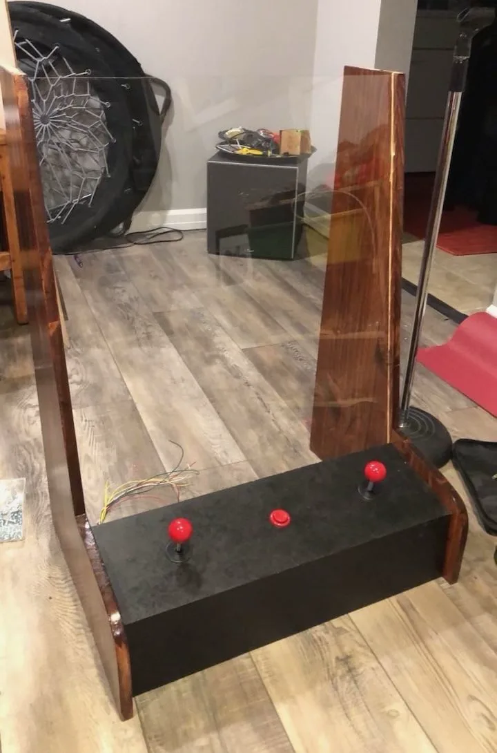
Control panel and acrylic sheet added
The top cabinet piece holds the eight-digit, seven-segment display scoreboard that lets the player know how many balls they have left, how much bonus is remaining for the current hole, and what their total score is so far. It makes it obvious when they mess up with a courteous “OOPS” displayed when they miss the target hole.
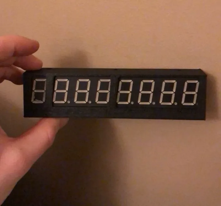
The seven-segment display in a 3D printed mount
Back view of the display modules in the part
Electronics
The brains of the machine is an Arduino Uno, an easy-to-use programmable microcontroller. The player inputs (start button, left joystick, right joystick) are simple microswitches, and their signals get sent to the Arduino. The Arduino also gets input from 11 IR sensors that detect where the ball is. These inputs get processed by the microcontroller which triggers the appropriate outputs. It can talk to the motor drivers which control the stepper motors that tilt the bar, it can play sound effects via an MP3 player module, it can individually flash ten LEDs, and it can write to the scoreboard through the SPI serial communication protocol.

Ball Sensors
In order for the Arduino to know which hole the user got the ball in, some sort of sensor is required. A sensor behind each hole, though, would be far too complex. In reality, only 11 sensors are needed: one for each of the ten target holes, and one for the ball gate at the bottom of the playfield. If the gate sensor is triggered without the proper target hole sensor being triggered prior, the machine knows the user got the ball in the wrong hole.
The original game utilizes physical microswitches, but I found it hard to place them in a way where they would reliably trigger, especially since the ball isn’t very heavy. After trying a few other options, I settled on pairs of infrared (IR) sensors. Think of a garage door sensor: one component emits infrared light and the other receives it. When the beam is broken by the ball going through the hole, the sensor is triggered. When the infrared light level falls below a certain threshold, a voltage drop occurs, which is then amplified using a transistor to a 5V signal suitable for the microcontroller.
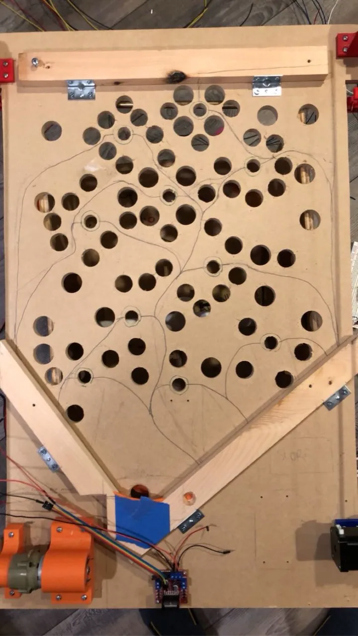
Wire paths planned out in pencil for the IR hole sensors
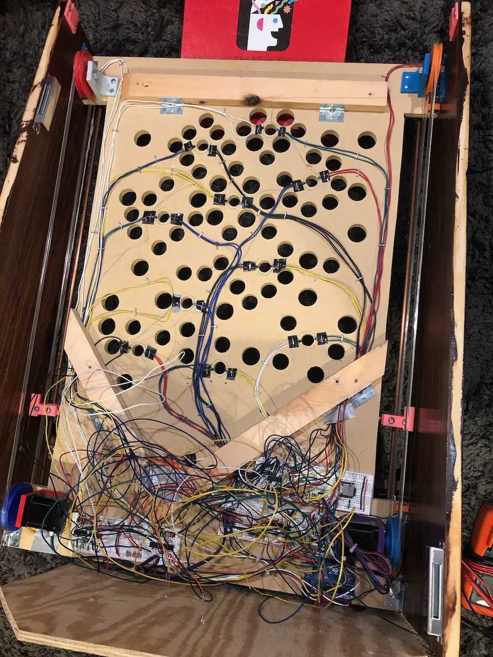
All IR sensors soldered to wires and neatly stapled to the playfield
Lights
The user is shown which target hole to aim for by a blinking light behind it. The original game has special mounts that hold the lamps behind the holes, but in my version they’re simply fixed into small drilled holes in the wooden panel that stops the balls from falling out of the machine.
All 20 wires for the LEDs originate from a protoboard (solderable breadboard) that houses the necessary resistors and a digital IO expander. The Arduino Uno doesn’t have enough IO (inputs/outputs) to accommodate Ice Cold Beer, so we used two expansion chips that utilize the I2C serial communication protocol to give the microcontroller access to more inputs and outputs.
I decided to add some light shows to my version, another thing the original game didn’t have. When the player loses all three balls, they’re greeted with a display of flashing lights synchronized with the “Game Over” music. A similar but more extravagant show is played when the player gets to the tenth hole. Each “frame” of a light show is defined as a boolean array with ten values. Each index of the array corresponds to one of the ten lights, and the boolean (0 or 1) value corresponds to the light state: off or on. Then, the code just needs to know the frequency it should iterate through and display the frames at. By making this a nice multiple of the bpm of the song, I can make the lights match up exactly with the music. I wrote a simple Python script to take a text file of frame information (easiest way for me to construct the light show), parse it, and convert it into C++ arrays that can be compiled with the Arduino code.
"Game Over" light show (turn up volume)
"Good Game" light show (turn up volume)
My most recent addition to Ice Cold Beer was to add an LED light strip to the inside of the cabinet to light up the playfield at night. It operates on 24V, and I used a relay to toggle the light strip from the Arduino. Relays are neat devices that enable a low-power input signal to control a high-power circuit. In this case, they use electromagnetic switches internally.
Motor Control
The original machine uses geared DC motors to actuate the left and right sides of the tilting bar. The two main issues is that they’re considerably noisy, and difficult to control precisely. Although I tried DC drill motors at first, I ended up using standard NEMA 17 stepper motors. In this application, they can be run much quieter, can be controlled precisely, and have a small form-factor while still providing the power I needed.
Stepper motors work by advancing the inner rotor one “step” at a time. The motors I used have 200 steps per revolution, so each step is a 1.8 degree rotation. Because of their nature, the motors can be commanded to go to a specific position or run at a constant speed without the need for closed-loop feedback (sensors feeding back to the controller).
The Arduino spits out dir (direction) and step signals to the stepper drivers to control the motors. For example, when the left joystick is in the upward position, the corresponding microswitch will be pressed, the microcontroller will send a “high” digital signal to the dir pin of the stepper driver, and step signals at a constant frequency to the step pin, based on the predetermined motor speed. If that joystick is moved down, the signal going to the dir pin would change from “high” to “low”.
Let’s say the target linear speed of the sides of the tilting bar is (v) [mm/s]. To calculate the necessary speed of the motor to achieve this, we can use the relationship (v = \omega r), where (v) is the linear speed [mm/s], (\omega) is the angular speed of the motor [rad/s], and (r) is the radius of the pulley [mm]. Solving for (\omega), we get (\omega = \frac{v}{r}) [rad/s].
Our goal is to get (\omega) in units of [secs/step]. We can use simple dimensional analysis to perform the conversion:
Taking the reciprocal:
By plugging in our target value for (v) and other constants, we can determine how much time the microcontroller should wait between sending each step pulse.
For the motor drivers, we used TMC2208 drivers that have advanced microstepping capability and can drive the motors very quietly and with high precision.
There are four limit switches on the machine that act as end stops. When the bar is fully extended to one extreme, a limit switch is closed, and the motor is stopped. Since the motors are steppers, only two limit switches are necessary since the machine homes itself at the bottom and knows how many steps it can travel before hitting the top of the machine. However, for redundancy and in case any steps are skipped, the machine has four.
Score
The scoreboard conveys three pieces of information to the player: how many balls they have left, how much bonus they have left on the current hole, and what their score is so far. Each player starts with three balls and loses one each time it falls into a wrong hole. If they reach 2000 points, they get one extra ball. At the beginning of every hole, the player starts with 100n bonus, where n is the whole number. At hole one they start with 100 bonus, at hole two 200, at hole three 300, and so on. Every few seconds, their bonus timer ticks down by ten points, and whatever is remaining of the bonus timer when they reach the hole is added to their score. So, the longer they take, the less points they receive.
The score is shown to the user via two four-digit seven-segment displays. The first digit represents the ball count, the next three represent the bonus, and the last four represent the score. Instead of having to individually address each segment of each digit from the Arduino, we used a special chip that operates on the SPI protocol and can address each segment itself. In other words, all the Arduino has to do is say “set digits 4-7 to 5200”, and the chip handles setting the appropriate segments to display that.
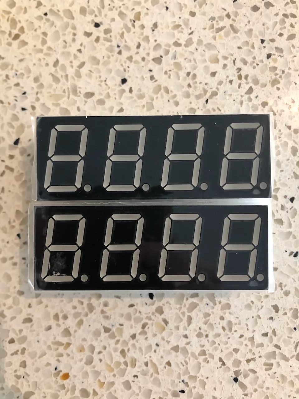
The two four-digit seven-segment display modules
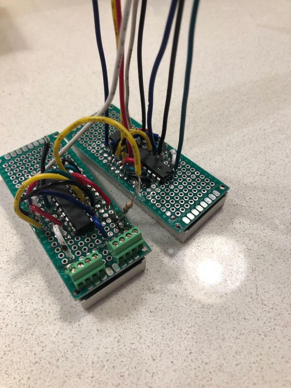
The display modules soldered to protoboards with MAX7219 chips and daisy-chained power/communication
Remastered Audio
I wanted to keep the sounds of the original game, but I was unable to find clean recordings of them online (probably because they were all taken in noisy arcades). I ended up using a MIDI keyboard and GarageBand to recreate the sounds, adding some custom harmonies. I used a plugin to make the sounds “8-bit”, and I’m pretty satisfied with the result.
We loaded all the sounds, including a “beer pouring” sound that was definitely not in the original game, onto an SD card that the MP3 module could read. The Arduino’s job is simply to tell the module which track to play, and the module plays it through a car speaker in the back of the cabinet with its built-in 3W amplifier.
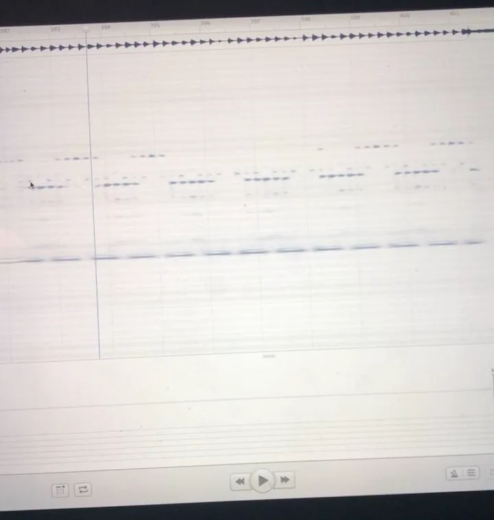
I used an application on my Mac to analyze the recordings of the original sounds I had to figure out which notes were played, as I don’t have perfect pitch. The joystick sounds were especially clever.
Each joystick movement plays a different note in a “telephone ringing style”. Pushing the left joystick up plays A3, left joystick down plays C#3, right joystick up plays C#4, and right joystick down plays E3. Each of these are notes in an A major chord, so any combination of these movements make for nice harmonies. Instead of overlaying two audio files and playing both together, which the MP3 module wasn’t capable of, I made separate audio files for each combination of movements.
For some of the tracks, I wrote out the sheet music in MuseScore and exported the tracks to MIDI for further editing in GarageBand.
Custom PCBs
My father, with his electrical engineering background, designed the circuit schematics. We started with breadboard prototypes, which worked but were unreliable and messy. If something went wrong, it was nearly impossible to debug the issue.
I decided to design my own printed circuit boards (PCBs) to neaten everything up (and c’mon, having your name on a circuit board is pretty legit).
I started by creating a digital representation of the circuit schematics online. Here, I defined how each component was interconnected with each other.

The next step was to take that schematic and create an actual PCB layout with the proper holes to solder the components to. A footprint of a component defines its shape on a board and its hole layout. If these disagree with the physical components, they won’t fit properly on the PCB. I ended up having to make many custom footprints to perfectly resemble the components I had. Within the PCB editor, I laid out the traces, which are the physical copper connections that live inside the PCB. Each PCB I designed had two independent layers of copper traces, and it was a fun challenge to lay out each board without overlapping traces.
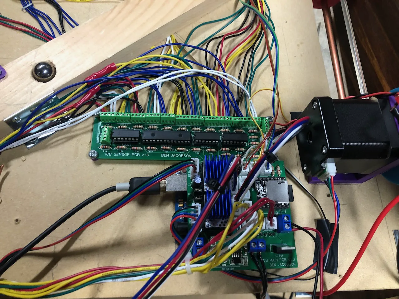
The main circuit board, which I named “ICB Main PCB” is actually designed to sit right on top of the Arduino Uno, sort of like a shield. Its job is to have clearly labeled terminals for the main inputs/outputs that internally route to the proper pins of the microcontroller. It also directly houses the two stepper drivers and MP3 audio player. All connections to external boards are made with removable JST connectors that I crimped by hand.
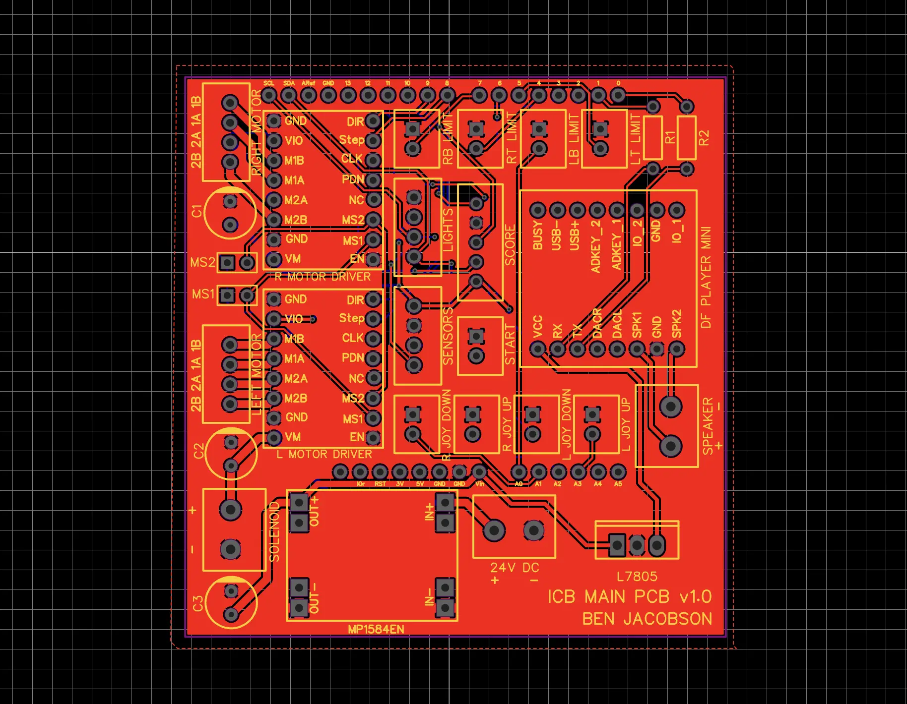
Main PCB layout
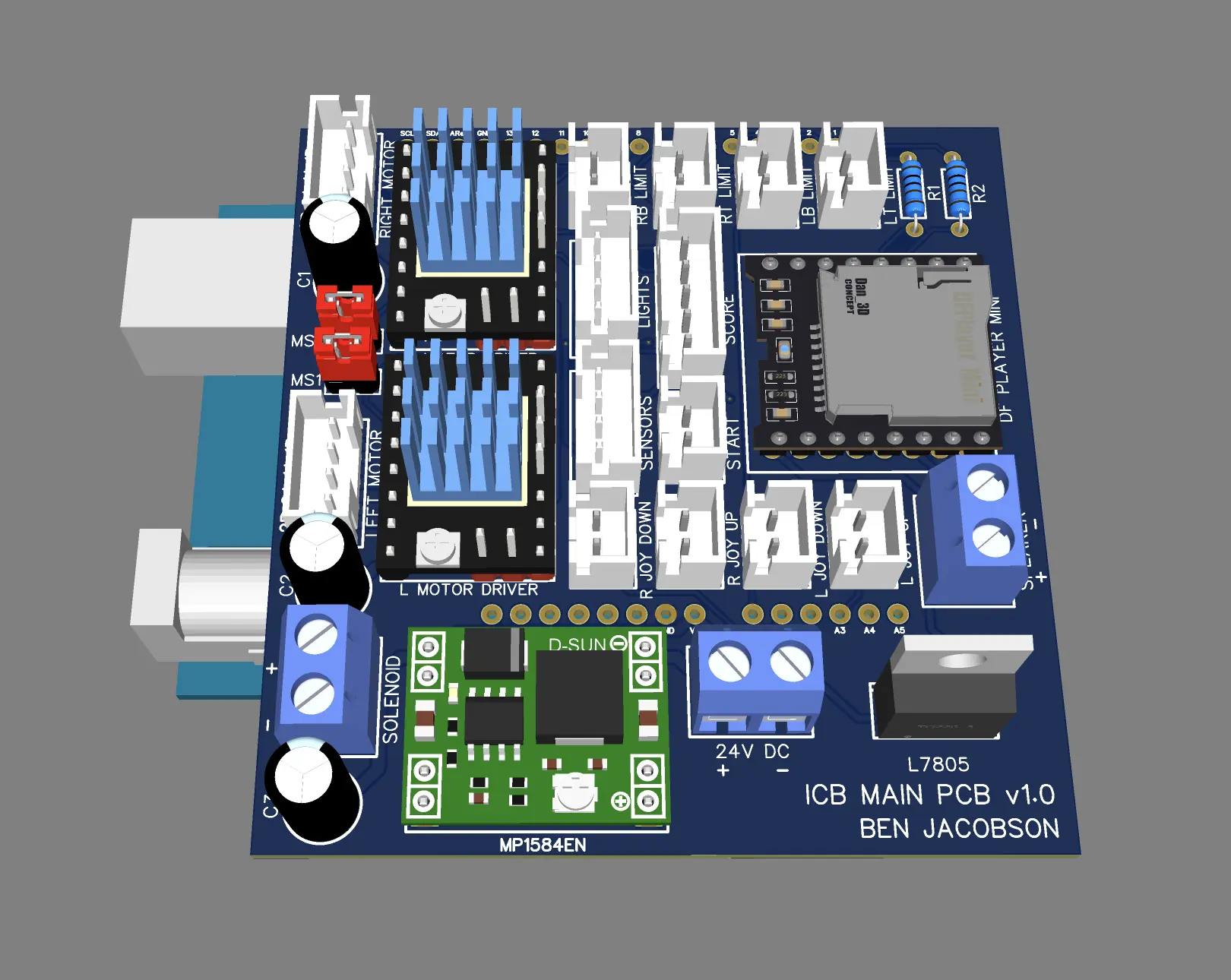
3D rendering of Main PCB with its components
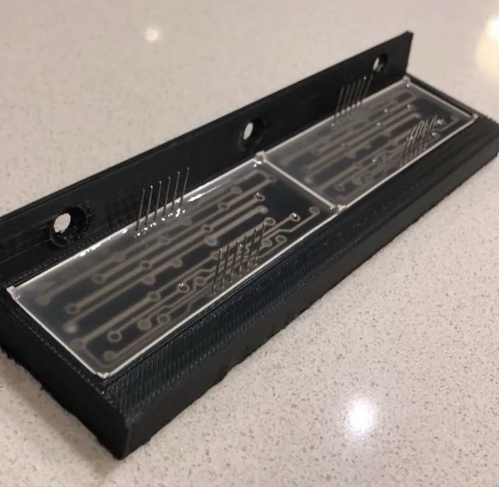
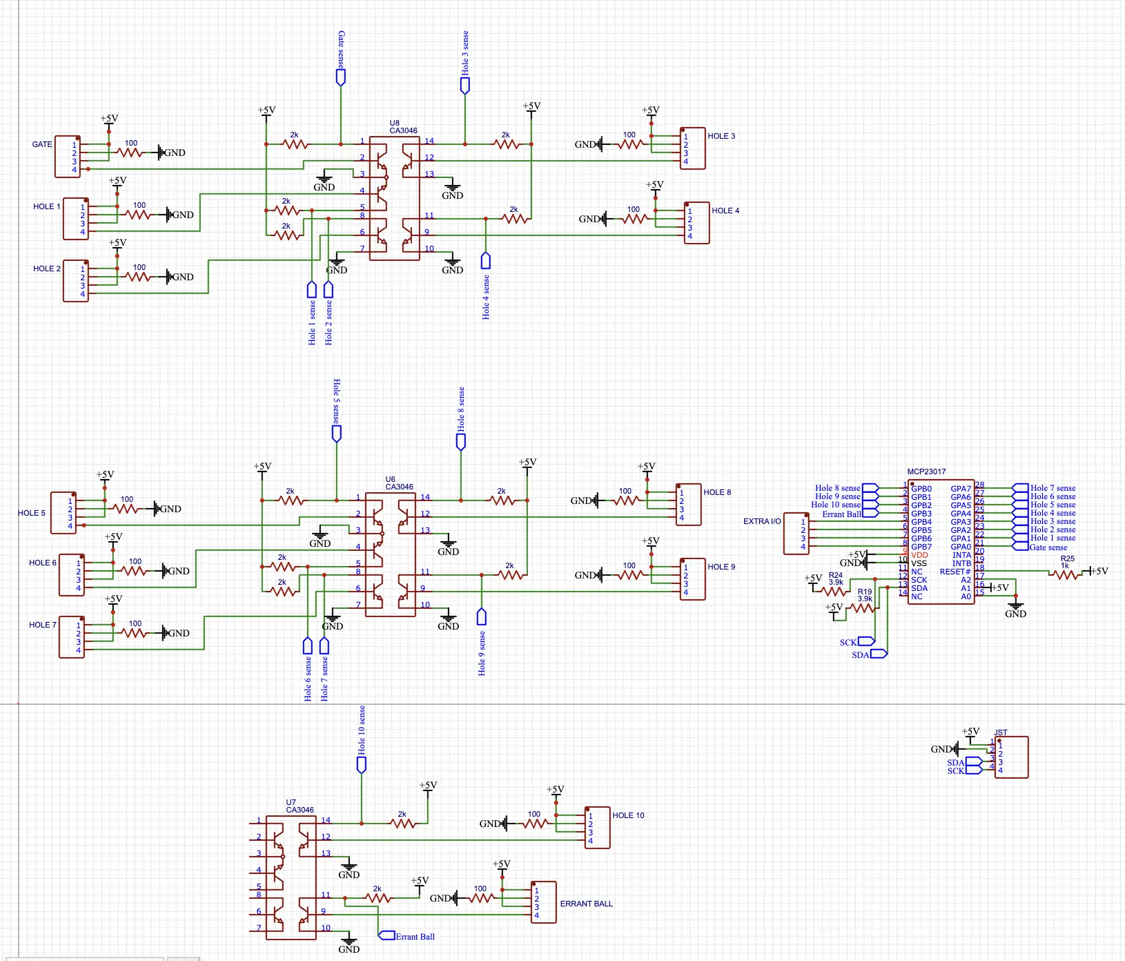
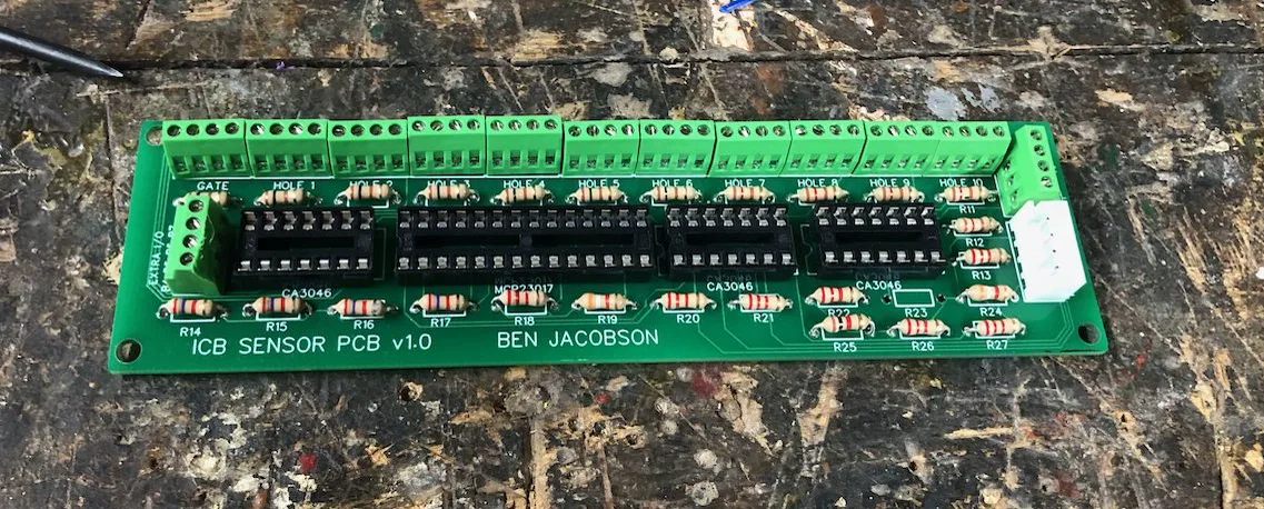
Another circuit board, which I named “ICB Sensor PCB” is responsible for dealing with all of the infrared sensors for the target holes and gate hole. Each pair of IR sensors connects to a neatly labeled screw terminal with the proper polarity indicated via a silkscreened diagram. The board has all the proper resistors for the IR emitters and the transistor array integrated circuit chips that amplify the signals from the receivers. Lastly, it’s home to an IO expander, just like on the light protoboard, so the only connection between the sensor PCB and Arduino is a two-wire I2C bus and 5V power.
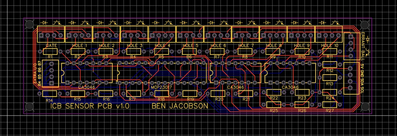
Sensor PCB layout

3D rendering of Sensor PCB with its components
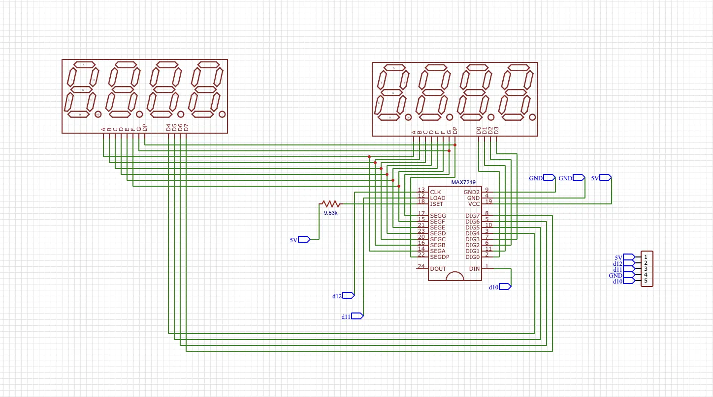
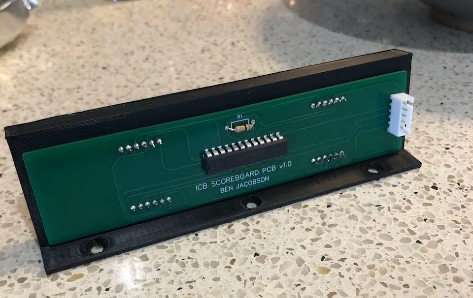
The last circuit board, which I named “ICB Scoreboard PCB” houses the two four-digit seven segment displays and MAX7219 driver chip that controls them. This board slots directly into the 3D printed scoreboard mount, and it only has a five-wire connection to the Arduino.
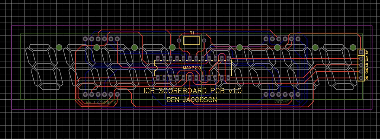
Scoreboard PCB layout
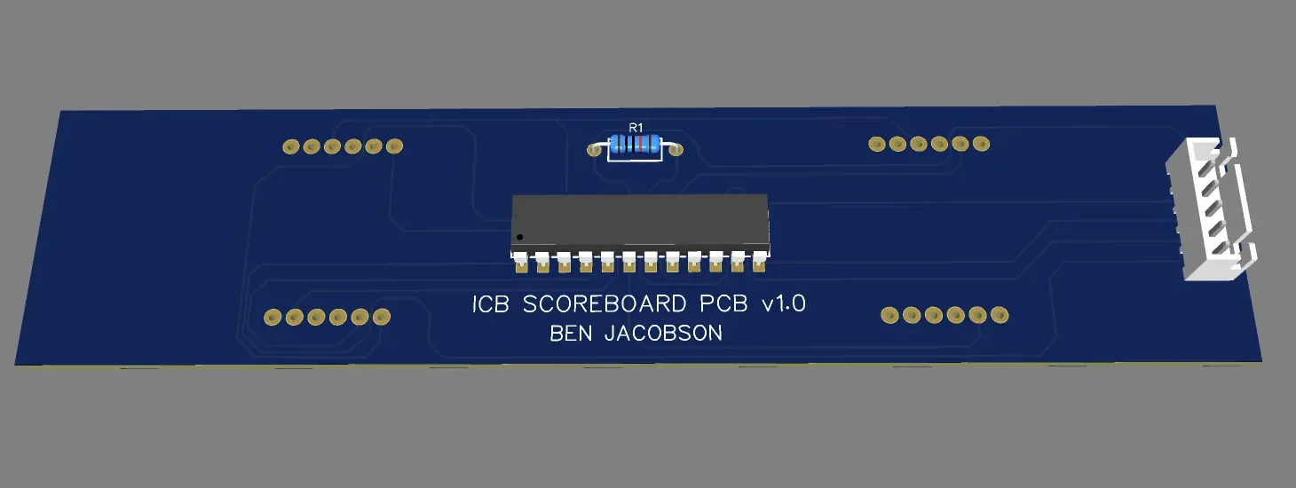
3D rendering of Scoreboard PCB with its components
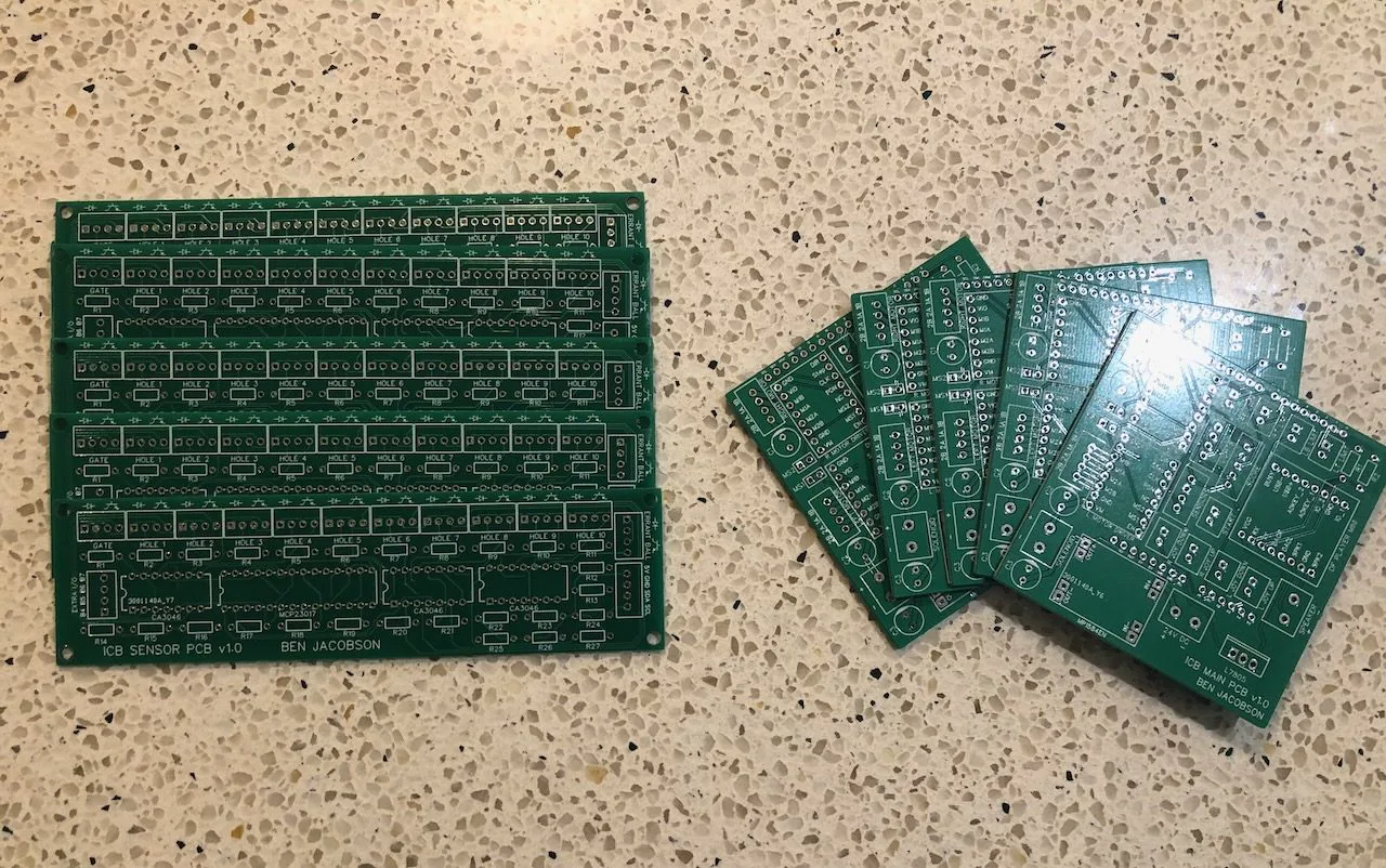
I ordered the PCBs from Hong Kong, and believe it or not, all three worked on the first try. All I had to do was solder the pin headers and components, mount the boards to the machine, and flick on the power.
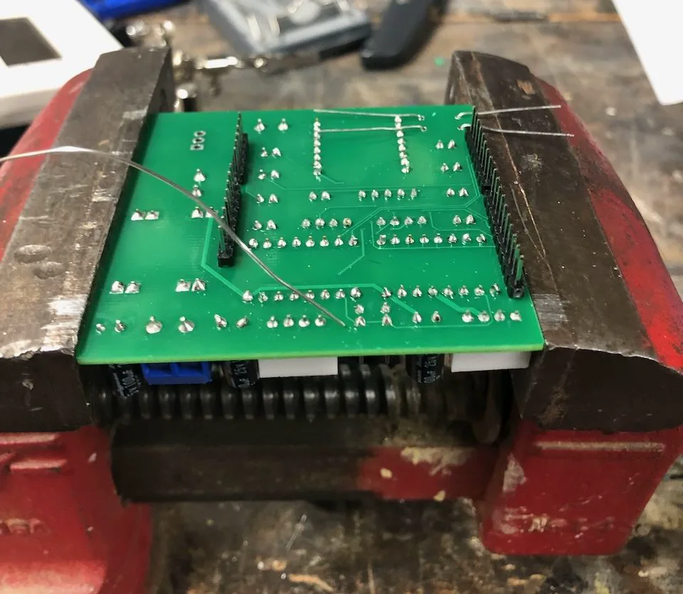
Components being soldered to Main PCB sitting in vise
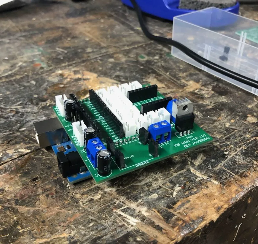
Main PCB with all non-removable components attached (Arduino underneath)
Power
The entire machine is powered off of a 24V DC, 3.5A power supply which operates on a 120V AC input that runs through a power switch. The 24V power is routed directly to the stepper drivers and the relay for the light strip since those devices are designed to operate at that voltage. The rest of the components, however, operate at smaller voltages. We used a voltage regulator to step down the 24V to 12V to power the Arduino. All other devices operate off of 5V, which is supplied to them via the Arduino’s built-in regulated 5V output.
Software
Introduction
Most code for Arduino is written in C++ and compiled to run on the on-board microcontroller. There’s a set of instructions designed to be executed once on startup (setup), and another set designed to be executed continuously afterward (loop). The Ice Cold Beer source code is centered around two main ideas: non-blocking code and state machines.
What is Non-Blocking Code?
In Arduino-based environments, the main loop repeats indefinitely, and it’s important for each loop iteration to be as quick as possible, since there are many things that the microcontroller needs to “check” continuously. This is the concept of non-blocking code. Blocking code is when you have pauses in the main loop that prevent it from executing quickly.
For example, here’s how you can make an LED blink with blocking code:
void setup() {
    pinMode(LED_BUILTIN, OUTPUT);
}

void loop() {
    digitalWrite(LED_BUILTIN, HIGH); // turn on built-in LED
    delay(1000); // pause 1 sec
    digitalWrite(LED_BUILTIN, LOW); // turn off built-in LED
    delay(1000); // pause 1 sec
}This is great if that’s all you need to do. But if you need to constantly check or update things, this won’t work. Instead, you need some way of keeping track of the time that has elapsed since some start event to determine whether or not to take action. Thankfully, Arduino libraries like BlockNot take care of this for us.
#include <BlockNot.h>

BlockNot lightTimer = BlockNot(1000); // initialize a BlockNot timer object with a time of 1000 ms
bool lightState = 0; // initialize a boolean variable to keep track of light state, start with off state (0)

void setup() {
    pinMode(LED_BUILTIN, OUTPUT);
}

void loop() {
    if (lightTimer.triggered()) {
        lightState = !lightState; // invert the light state
        digitalWrite(LED_BUILTIN, lightState); // set the light to the new light state
    }
}The Ice Cold Beer source code has many timers:
BlockNot _ledTimer(LED_TIMER_TIME); // timer for blinking target hole
BlockNot _bonusTimer(BONUS_TIMER_TIME); // timer for counting down the bonus
BlockNot _heartbeatTimer(HEARTBEAT_TIMER_TIME); // timer for reducing the bonus while playing
BlockNot _startButtonTimer(START_BUTTON_TIMER_TIME); // used to check if button held for 0.5s
BlockNot _idleTimer(_idleTimerTime[0]); // timer to determine when to bump up bar
BlockNot _solenoidTimer(SOLENDOID_TIMER_TIME); // used to let the ball settle for a bit when it's first detected at the solenoid
BlockNot _NinetyNineBottlesTimer(LENGTH_OF_99_BOTTLES_TRACK); //used to disable other sounds while this one plays
BlockNot _scrollTextTimer(SCROLL_TEXT_TIMER_TIME); // used to scroll "ICE COLD BEER" on display
BlockNot _attractModeLEDTimer(ATTRACT_MODE_LED_TIMER_TIME); // defines the length of one frame for the attract mode lights
BlockNot _tenthHoleTimer(TENTH_HOLE_TIMER_TIME); // defines the length of one frame for the 10th Hole light show
BlockNot _gameOverTimer(GAME_OVER_TIMER_TIME); // defines the length of one frame for the Game Over light showWhat is a State Machine?
A state machine is a neat way to keep track of what’s currently happening, what might happen next, and how to transition to the next event. In any given “state” of a state machine, there’s a defined set of actions to complete while in that state, and a defined set of other states that can be triggered next.
For example, let’s consider a soccer player. This soccer player can have the states: “dribbling”, “ready to shoot”, and “shooting”. While the player is in the “dribbling” state, they’ll dribble the ball and check to see if they’re close enough to the goal to take a shot. If they’re within 10 yards of the goal, the state will change to “ready to shoot”. In the “ready to shoot” state, the player will keep dribbling and monitor the defenders to make sure there’s a clear shot. If the defenders are out of the way, the state will switch to “shooting”. In the “shooting” state, the player can finally take their shot. State machines are convenient ways to define which actions can happen when.
Setup
The “setup code” runs one time as soon as the game gets powered on. Almost all of this code consists of initialization. The scoreboard is powered up and cleared, the pin modes for all inputs and outputs are set, the motor max speeds are defined, some timers are started, and the game state is set to attract mode.
Besides the “setup code”, many global variables are defined. Some are constants that define things like timer times, motor speeds, and states. Others are variable and keep track of things like the user’s score, how many lives they have left, etc.
Main Loop
The main loop runs continuously and repeats as fast as possible (non-blocking). There are some things that happen each loop regardless of the machine’s current state. Every loop, the start button and the four limit switches are checked. In attract mode, the user can press the start button once to start the game, and in any other state, the user can hold it down. Any time a limit switch is triggered, the corresponding motor is stopped immediately.
serviceStartButton(); // this function reads input from the start button and acts accordingly

// read the state of each limit switch and update the corresponding boolean
_right_bottom_limit = !digitalRead(RIGHT_MOTOR_BOTTOM_LIMIT_PIN);
_right_top_limit = !digitalRead(RIGHT_MOTOR_TOP_LIMIT_PIN);
_left_bottom_limit = !digitalRead(LEFT_MOTOR_BOTTOM_LIMIT_PIN);
_left_top_limit = !digitalRead(LEFT_MOTOR_TOP_LIMIT_PIN);


if (_left_bottom_limit || _left_top_limit) { // if either of the left limit swiches are being pressed
    left_motor.stop(); // stop the left motor
}
if (_right_bottom_limit || _right_top_limit) { // if either of the right limit switches are being pressed
    right_motor.stop(); // stop the right motor
}
Besides these essential actions, all other actions that the machine can take depend on the current state. The Ice Cold Beer source code has the following game states:
enum gameState {
  gsBallOnPlayfield, // while ball is on playfield and user is playing
  gsBallEnteredTargetHole, // ball has just entered target hole
  gsBallAtGate, // ball is at the ball gate
  gsAttractMode, // game is in attract mode
  gsBallAtSolenoid, //ball detected at base of solenoid
  gsBallInSolenoidTube //solenoid fired but ball has not yet reached gate
};
While the game is in the “gsBallOnPlayfield” state, the following actions are taken:
- The input to the joysticks are constantly read and motor commands and audio commands are sent accordingly
- The current target hole sensor is monitored, and the ballInTargetHole() function is called if the sensor is triggered
- The ballInTargetHole() function plays the correct audio track, counts down the bonus into the score, clears the hole lights, and retrieves the ball at the gate. Parts of this routine are blocking since nothing else needs to happen simultaneously
- The gate sensor is monitored, and the game state is set to “gsBallAtGate” if it’s triggered. The machine knows the ball went in the wrong hole because it’s the only way for the gate sensor to be triggered. If the ball went in the correct hole, the state would’ve changed before the gate sensor was triggered.
- The LED timer is monitored, and the current target hole light blinks appropriately
- The bonus timer is monitored, and the bonus counts down every four seconds until a hole is reached. The “Heartbeat” sound is played in sync with the bonus counting down.
While the game is in the “gsBallAtGate” state, the bar is sent down to retrieve it until the gate sensor detects that the ball has left the gate, when the state is changed back to “gsBallOnPlayfield”. While the game is in the “gsAttractMode” state, the serviceLEDPattern() function gets called repeatedly which uses a BlockNot timer to iterate through a pre-determined sequence of light states that creates a nice visual effect. A very similar function is called to scroll through text (a char array) on the scoreboard. There are many other subtleties involved in the code, but hopefully this overview sheds enough light on the inner-workings.
If you made it this far, I really appreciate it. I’d be happy to answer any lingering questions you may have: Contact Me.