Tennis Ball Machine
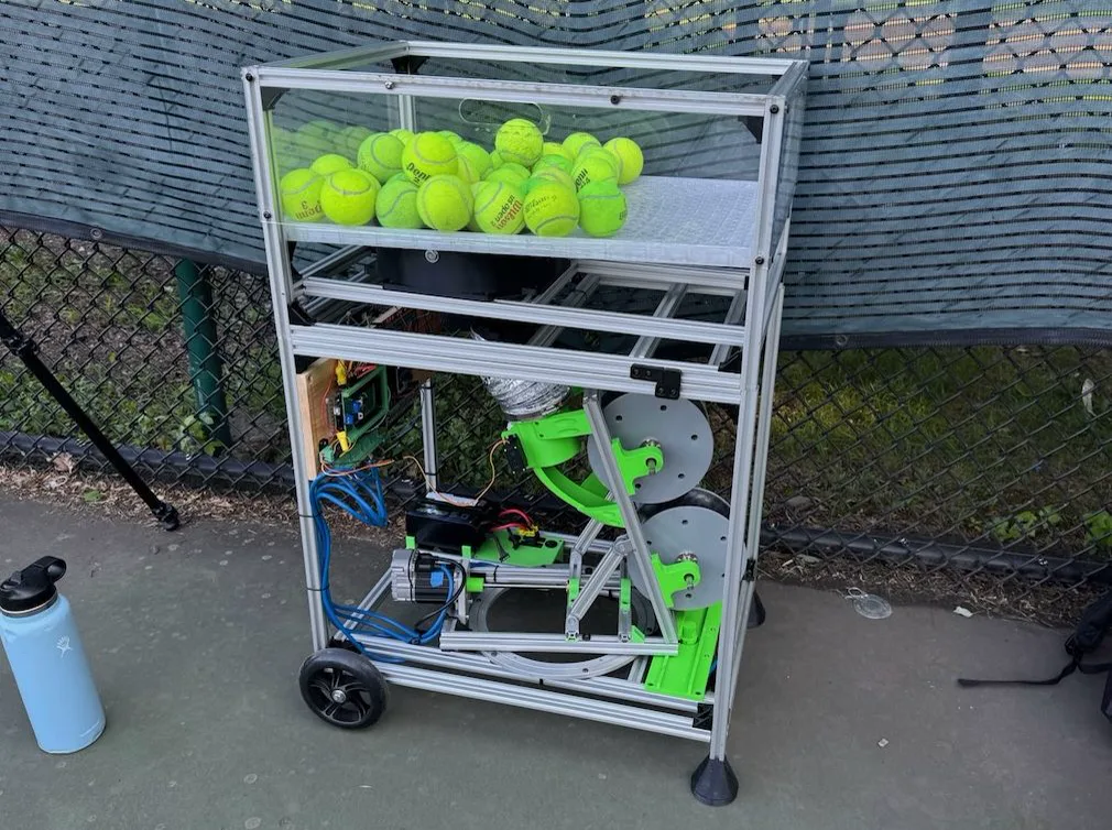
Custom ball machine complete with pan, tilt, speed, spin, and feed rate control
looping video of it on the court
Background
Motivation
My family all loves to play tennis. In 2022, my father brought up the idea of making our own tennis ball machine that could shoot balls at us from across the court. Besides it being fun to build, it would be useful for solo practice.
Requirements & Constraints
We decided the machine would need computer-controlled pan (horizontal aim), tilt (vertical aim), and ball speed, spin, and feed rate. It also needed to be transportable by one person, fit in our car, run on battery power, and cost less than comparable machines on the market.
My Role
I started the project responsible for the mechanical side, with my dad handling the electrical. As the build progressed, I eventually took over and handled all aspects of the machine as a solo project.
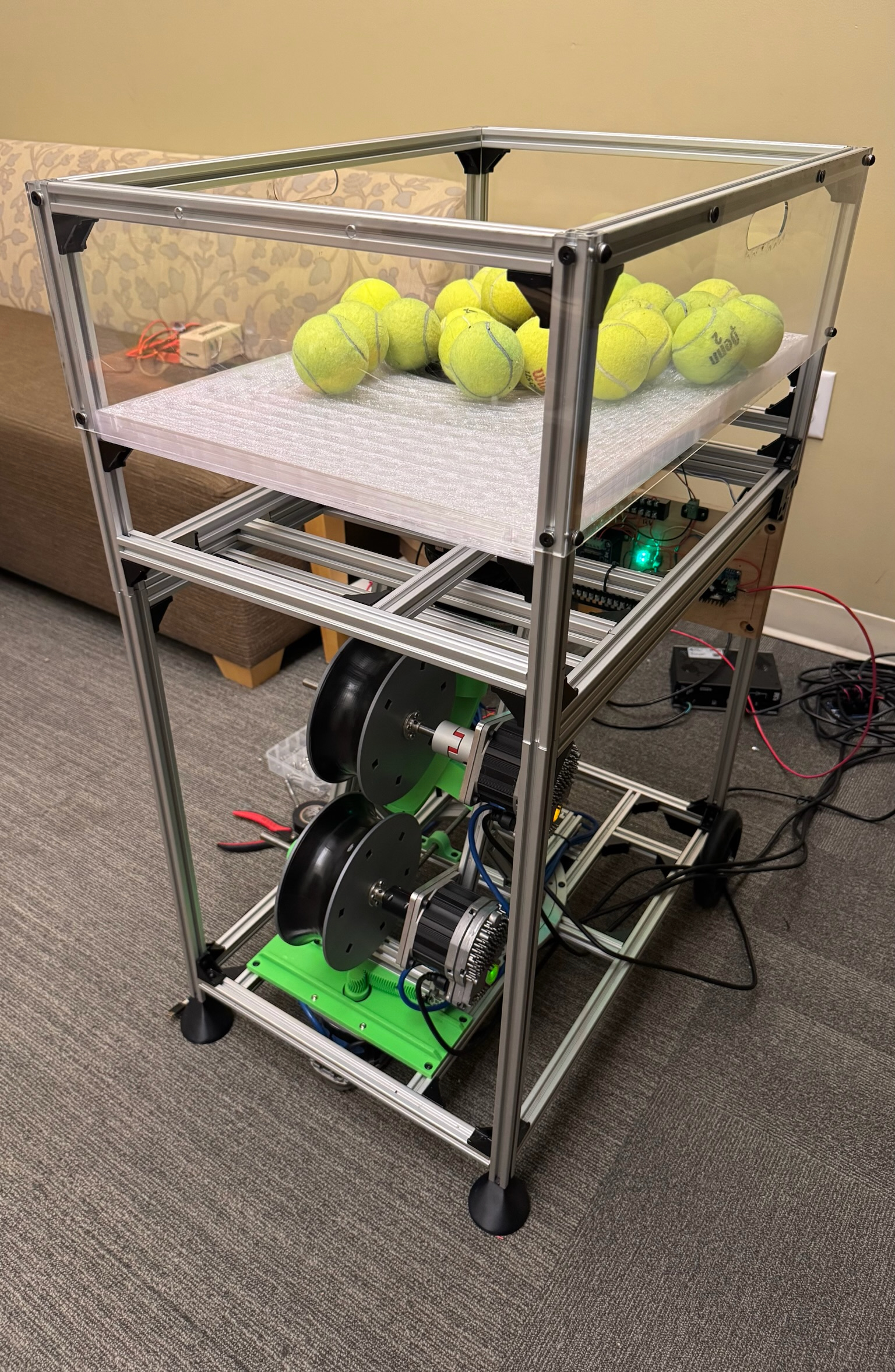
Build
Result
Deep Dive
Mechanics
Ball Hopper & Carousel
The ball hopper is responsible for two things: a. storing all of the balls that will be used during play, and b. guiding the balls to the next sub-system, to eventually be fed to the throw wheels. Because the end result is to have the balls form a linear queue before entering the throw wheels, I considered storing the balls in the hopper in a similar, linear fashion.
One idea was to have a spiral that the balls would be feed into by the user and rest in before being set to the wheels. However, this requires the user to fill up the balls neatly instead of being able to dump them in, and a spiral doesn’t have a great packing density in the hopper. Another consideration was to have a “magazine” style system that utilized pre-existing tennis ball pick-up tubes. The user would fill up a tube, lock it onto the machine, and then it would index the tube and remove balls one-by one. However, this would require multiple tubes since each only has a ~20 ball capacity, and would likely be cumbersome to the user.
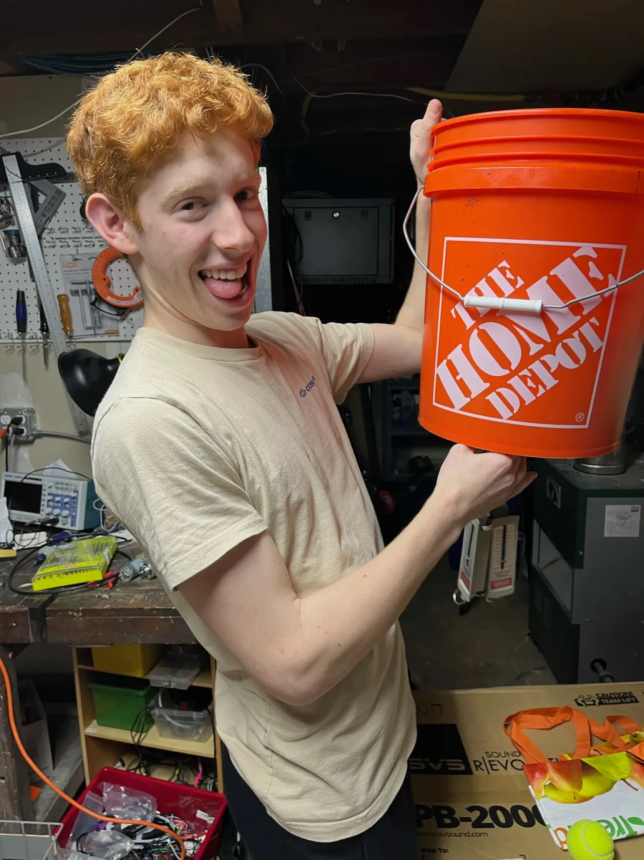
The concept I settled on was a simple hopper that holds all balls in a disorganized way, and then passes them into a ball carousel to extract each ball one at a time. The carousel has holes that fit one ball each, and as it rotates, the balls in the carousel line up with the exit hole and get released. This is the most common method that machines on the market use today, based on my research. My first prototype used a Home Depot bucket. It worked in small capacities, but once more balls were added, the down pressure from all the balls caused friction and jams. This concept was too vertical: it concentrated all the balls directly above the carousel instead of spreading them out to the side.
My second prototype used a much wider, rectangular box. This allows the balls to spread out horizontally, and the angle of the ramp controls how much downwards force they induce on the carousel (now proportional to the sine of the angle instead of the full weight). But besides that, it also gives balls room to escape horizontally if the carousel gets too crowded. Before, if balls got stuck, they couldn’t spread out because of the tight, vertical walls of the bucket.
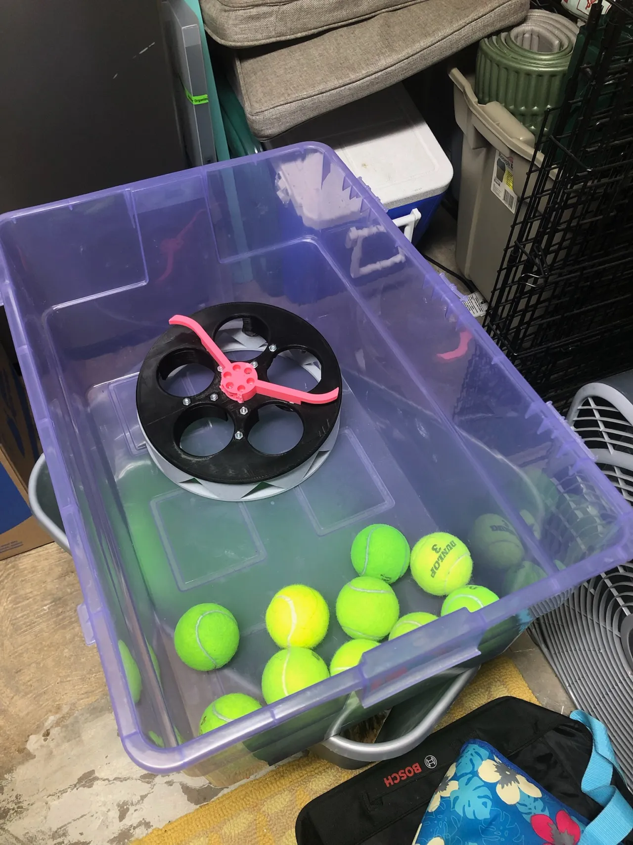
This worked very well, but still had one key issue: when the ball over the exit hole got released, there was nothing preventing another ball from taking that position, and either causing a double-fire or a jam. The solution was to add a TPU flap that sits over the exit hole and does not allow a ball to enter from the top. TPU is a flexible material that can be FDM 3D printed, and in this case avoids jams by flexing out of the way if necessary.
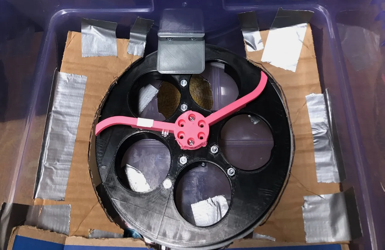
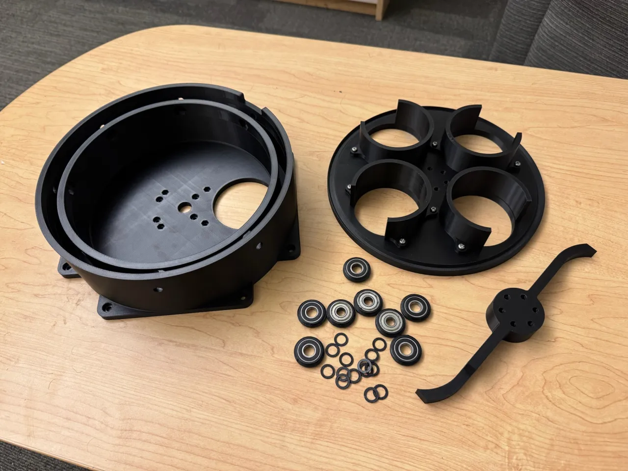
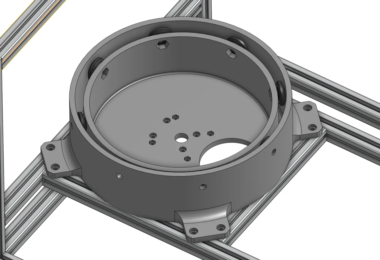
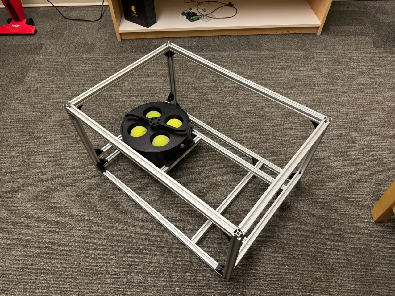
When I moved onto the aluminum frame build, I slightly redesigned the carousel.
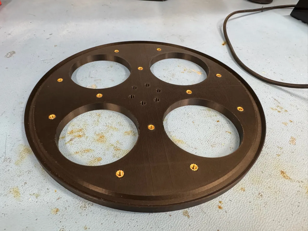
The carousel itself is comprised of a few key components: the housing, the shaft, the disk, the rollers, the agitator, and the stop. The housing is the large 3D printed cylindrical part that mounts to the frame and houses all other components of the carousel. The bottom has a mount for the motor and an exit hole to release one ball at a time. The shaft couples to the output “D-shaft” of the wormgear-drive motor and is bolted onto to bottom of the disk to rotate it. The rollers are skateboard bearings with V-shaped wheels snapped onto them which nest into the matching V-shaped groove on the underside of the disk, allowing for smooth and stable rotation. The disk has 4 cups mounted to the underside which guide each ball around the carousel internally. The agitator is a simple arm that mounts on top of the carousel to “agitate” the balls as it spins, ensuring they move around and find their way into one of the holes in the disk. Without it, the disk could spin underneath th e balls without forcing them to move since the tennis ball felt on plastic is relatively low-friction. Finally, the TPU flap from the earlier prototype was replaced with the stop: a simple wire spanning across one hole, since there wasn’t a nearby wall to mount the flap to in the new design.
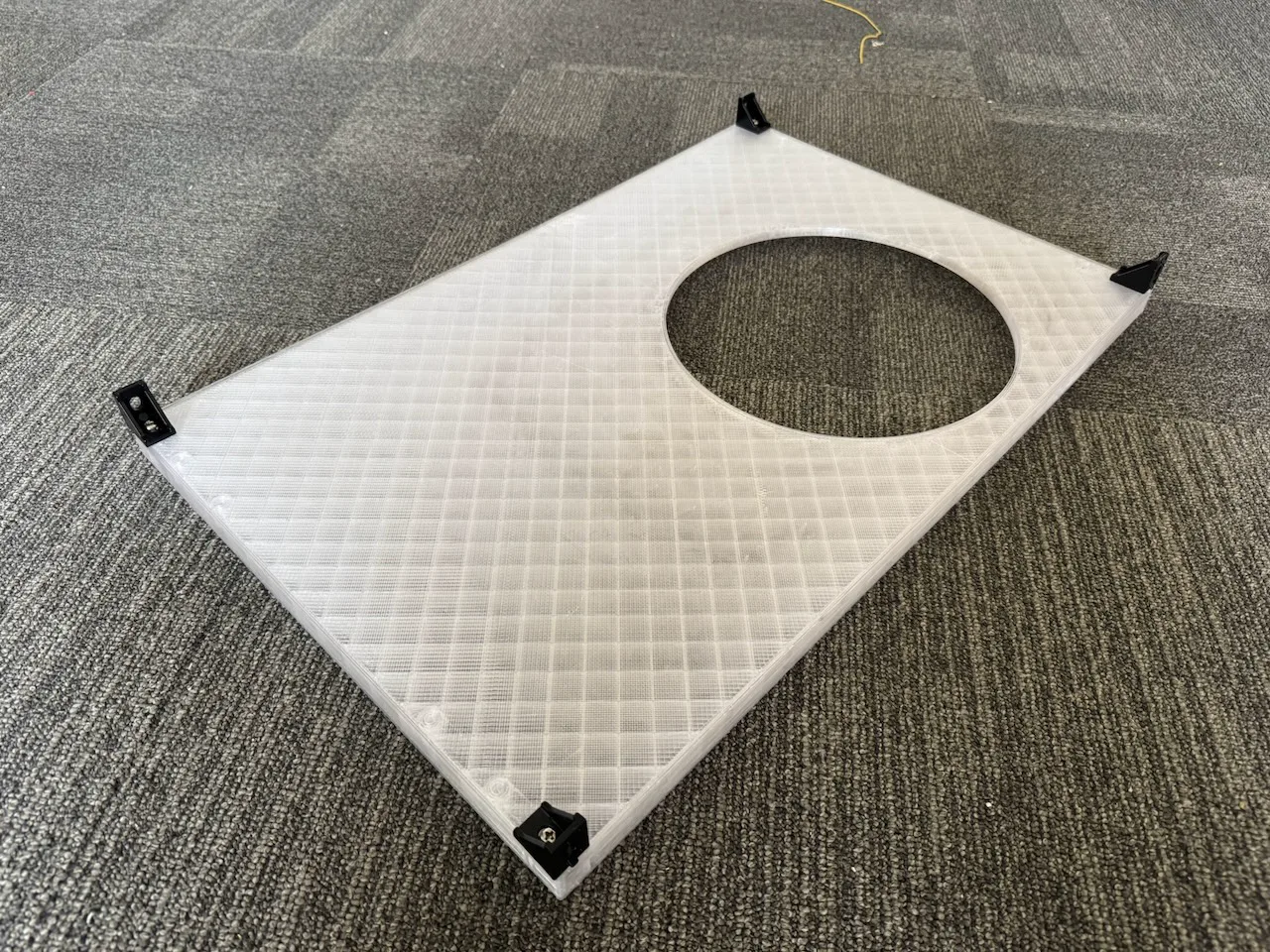
The cardboard ramps in the prototype worked surprisingly well, but I needed to find a more robust, permanent solution of course. A vacuum-formed plastic insert would be ideal, but would be expensive since I would need to make a one-time mold. I also considered stacking multiple sheets of foam and using a CNC router to cut out a smooth, continuous piece. I also considered laser cutting multiple pieces of thin plywood and combining them with 3D printed contours for the corners.
Ultimately, I decided to utilize the large-format FDM 3D printer on RIT’s campus and 3D print the entire ramp in one piece. To optimize for cost and reduce the load on the carousel, I opted for a very shallow loft angle. However, I forgot to account for the course layer lines of the low-resolution print, and balls were still able to get stuck if placed the right way. It works well enough for now, but will eventually be replaced.
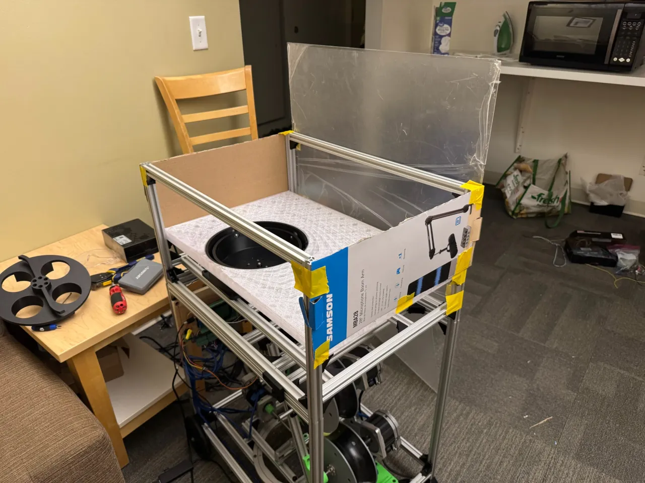
Also, once I moved from the plastic bin to the aluminum frame, I needed a way to enclose it to actually hold the balls. I laser cut some acrylic panels and bolted them on the four sides.
TODO: add info here about the anti-jam current sensing feature
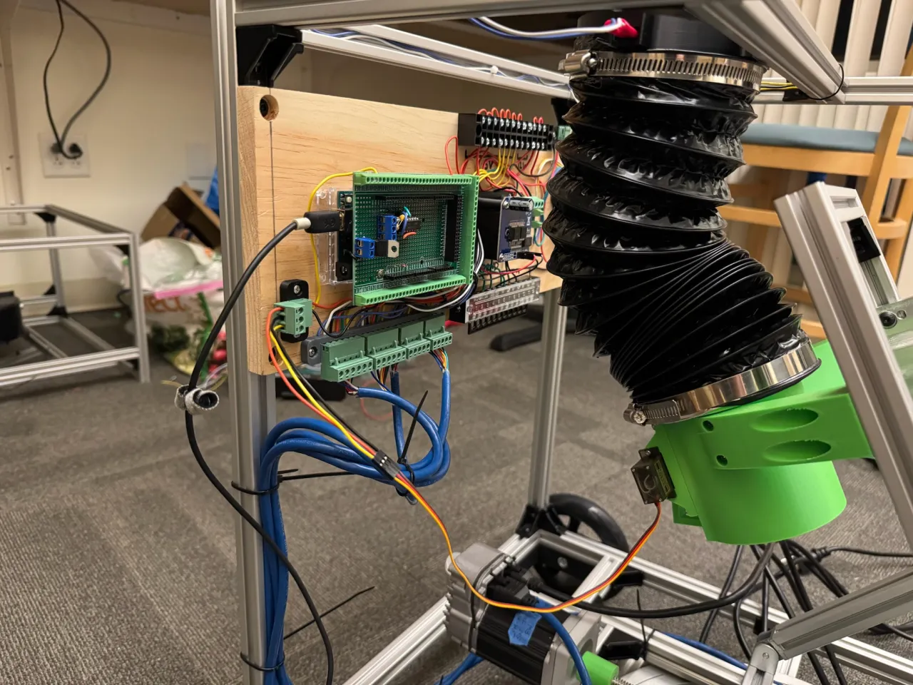
Ball Tube
Once a ball is realeased from the carousel, it needs to make its way to the feed ramp, and eventually into the throw wheels. However, since the entire throwing assembly can articulate in both pan and tilt, I couldn’t have a static pathway connecting the two subsystems. Instead, I opted for a flexible tube that can expand, contract, and flex to accommodate the wide range of end positions of the tube. To ensure that the tube would be capable of guiding the balls to any possible position, I spent a lot of time selecting the start position of the tube. The side-to-side position was selected to align with the throw wheels, and the front-to-back position as selected to make sure balls couldn’t get stuck in either of the tilt extremes. The ball carousel needed to line up with this placement, and the placement of the ball carousel drove the design of the ball ramp, so I had many design dependencies to work through.
The carousel is designed to spin at a constant rate (driver is fed a constant PWM value from the Arduino), but it’s not a closed loop system, so the speed could fluctuate, especially as the battery dies. I would need to add in an encoder or sensor of some sort for position/velocity feedback. But even if the carousel did spin at a constant rate, it’s possible (albeit rare) that some holes in the carousel are skipped. On top of this, the distance that the ball must travel from the carousel to the ball ramp depends on the position of the ramp, since it can tilt up and down.
Because I wanted to have precise control over the timing of each shot (to allow for advanced features like drills or hitting specified targets), and because of the way my specific Teknic ClearPath brushless servos work (read more on that below), I realized that the timing from the carousel alone wouldn’t be good enough.
I considered different options of how to improve timing from the ball carousel, or handle the ball feeding in completely different ways, but I couldn’t come up with a good, single-actuator solution. So, I decided to introduce a new component: the ball gate. The carousel is responsible for converting the resting balls in the hopper into a linear queue, and the ball gate is responsible for delivering each ball to the feed ramp with precise timing control (read more on the ball gate below).
This new addition also introduced a queue of balls in the ball tube. While this is good if you want to release multiple balls in quick succession, it can become a problem if they overflow. To prevent this, the machine needs to know how many balls are in the tube at any given time so it can stop the carousel from adding more if necessary.
The 3D printed part that the top of the tube clamps onto also has an IR breakbeam sensor, consisting of an emitter and receiver. When a ball enters the tube, the receiver no longer sees the IR light from the emitter, and the balls_in_tube counter is incremented by 1. When the gate is opened to release a ball, the counter is decremented by 1. At any given moment, if the current value of balls_in_tube is greater than the desired, the carousel is commanded to stop. And if the opposite is true, the carousel is commanded to spin (with smooth acceleration and deceleration built in).
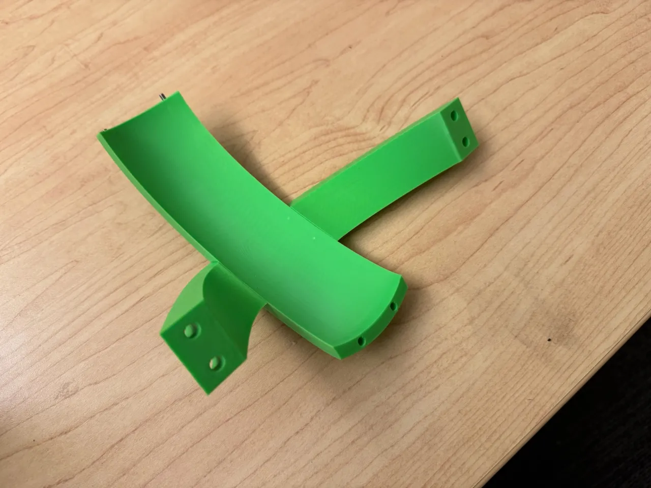
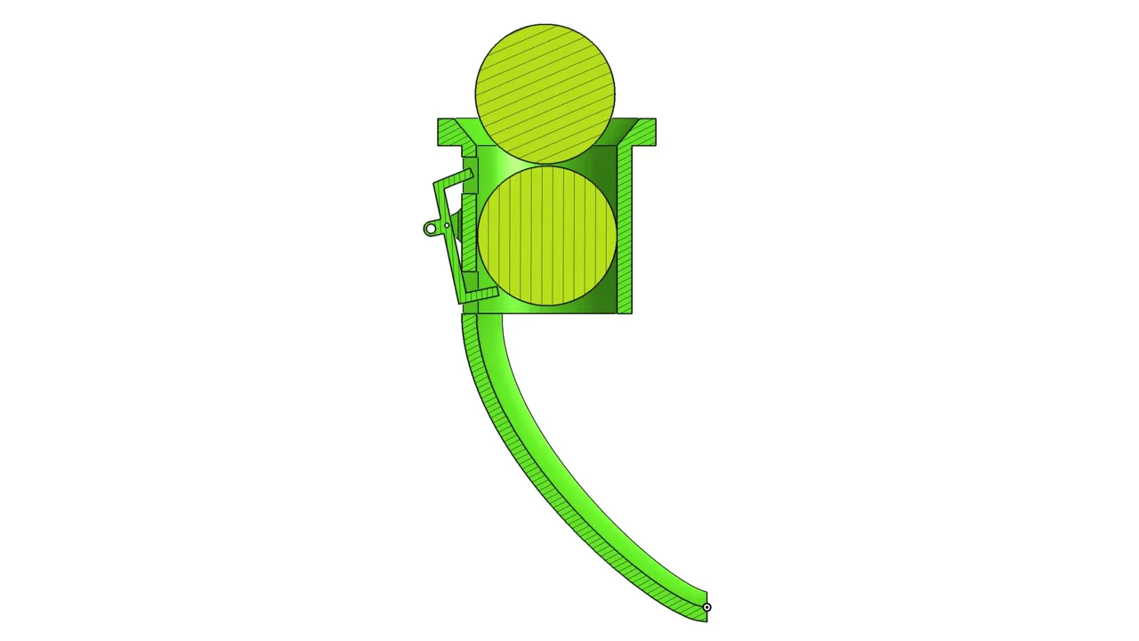
Ball Gate
The main component in the ball gate assembly is a 3D printed tube with a hobby-style servo motor attached. The servo drives a lever that pivots within a plastic tube. It uses a two-action release mechanism that allows one ball to drop while the next one is held out of the way. In the “closed” position, one ball is held in its “exit” position, while the next one rests on top of it. When the gate opens, that ball is released, and the top of the gate holds the next ball up and out of the way. When the gate resets back to its “closed” position, that next ball is allowed to drop and wait in its “ready” position, and the cycle continues.
The ball gate assembly also features connecting arms that bolt onto the tilting frame, and a ramp attached to the bottom, called the feed ramp, which is reponsible for guiding the balls into the throw wheels. This assembly, and many other 3D printed assemblies in this project utilize heat-set inserts which add strong internal threads into 3D prints, allowing me to screw them together and not worry about them stripping apart.